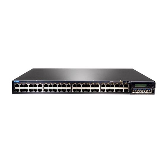
Juniper EX3200 Quick Start Manual
Hide thumbs
Also See for EX3200:
- Hardware manual (310 pages) ,
- Complete hardware manual (280 pages) ,
- Datasheet (8 pages)
Table of Contents
Advertisement
Quick Links
Quick Start Guide
EX3200 and EX4200
IN THIS GUIDE
Step 1: Begin | 1
Step 2: Up and Running | 7
Step 3: Keep Going | 8
Step 1: Begin
IN THIS SECTION
Install a Power Supply (If It Is Not Installed) | 2
Install a Fan Tray (If It Is Not Installed) | 3
Mount the Switch | 4
Connect Power to the EX3200 and EX4200 | 4
To install and perform initial configuration of a Juniper Networks
Two mounting brackets and eight mounting screws (provided)
Electrostatic discharge (ESD) grounding strap (not provided)
For AC power supply installation—An AC power supply (if not installed), an AC power cord with a plug appropriate for
your geographical location, and a power cord retainer (if not installed)
For DC power supply installation—A DC power supply (if not installed) and DC power source cables (12–14 AWG—not
provided) with ring lugs (Molex 0190700067 or equivalent—not provided) attached
Fan Tray (if not installed)
Ethernet cable with an RJ-45 connector attached (provided)
®
EX3200 or EX4200 Ethernet Switch, you need:
Advertisement
Table of Contents

Summary of Contents for Juniper EX3200
- Page 1 Install a Power Supply (If It Is Not Installed) | 2 Install a Fan Tray (If It Is Not Installed) | 3 Mount the Switch | 4 Connect Power to the EX3200 and EX4200 | 4 ® To install and perform initial configuration of a Juniper Networks...
- Page 2 Register product serial numbers on the Juniper Networks website and update the installation base data if there is any addition or change to the installation base or if the installation base is moved. Juniper Networks will not be held accountable for not meeting the hardware replacement service-level agreement for products that do not have registered serial numbers or accurate installation base data.
- Page 3 4. Push the locking lever up to its highest position (this action might pull the power supply in). Tighten the locking lever screw. Install a Fan Tray (If It Is Not Installed) CAUTION: When you are installing a fan tray, ensure that the fans face downward. 1.
-
Page 4: Mount The Switch
4. Have a second person secure the switch to the rack or cabinet by using appropriate screws. Connect Power to the EX3200 and EX4200 IN THIS SECTION Connecting EX3200 and EX4200 to AC power | 5 Connecting EX3200 and EX4200 to DC power | 6 NOTE: If you are interconnecting multiple switches as a Virtual Chassis, power on only one switch—the one... - Page 5 Connecting EX3200 and EX4200 to AC power To connect power to an AC-powered switch: 1. Squeeze the two sides of the power cord retainer clip and insert the L-shaped ends of the wire clip into the holes in the bracket on each side of the AC appliance inlet.
- Page 6 Connecting EX3200 and EX4200 to DC power To connect power to a DC-powered switch: Each DC power supply has four terminals labeled A+, B+, A–, and B–. The power supply is shipped with jumpers from the A+ input to the B+ input tied together and jumpers from the A– input to the B– input tied together.
-
Page 7: Step 2: Up And Running
Step 2: Up and Running NOTE: Before you begin the configuration, enable a DHCP client on the management PC that you connect to the switch so that the switch can obtain an IP address dynamically. NOTE: Read the following steps before you begin the configuration. Complete the initial configuration within 10 minutes by using EZSetup. -
Page 8: Safety Warnings Summary
See the complete EX3200 and EX 4200 documentation at https://www.juniper.net/documentation/product/en_US/ex3200 and https://www.juniper.net/documentation/product/en_US/ex4200. Safety Warnings Summary This is a summary of safety warnings. For a complete list of warnings, including translations, see the complete EX3200 and EX4200 documentation at https://www.juniper.net/documentation/product/en_US/ex3200 https://www.juniper.net/documentation/product/en_US/ex4200. -
Page 9: Power Cable Warning (Japanese)
Metal objects heat up when connected to power and ground and can cause serious burns or become welded to the terminals. Power Cable Warning (Japanese) The attached power cable is only for this product. Do not use this cable for another product. Contacting Juniper Networks For technical support, see: http://www.juniper.net/support/requesting-support.html... - Page 10 Juniper Networks, the Juniper Networks logo, Juniper, and Junos are registered trademarks of Juniper Networks, Inc. in the United States and other countries. All other trademarks, service marks, registered marks, or registered service marks are the property of their respective owners. Juniper Networks assumes no responsibility for any inaccuracies in this document. Juniper Networks reserves the right to change, modify, transfer, or otherwise revise this publication without notice.


