Table of Contents
Advertisement
Quick Links
NAF791 Series
User's Manual
No. G03-NAF791-F
Rev: 3.0
Release date: October 1, 2019
Trademark:
* Specifications and Information contained in this documentation are furnished for information use only, and are
subject to change at any time without notice, and should not be construed as a commitment by manufacturer.
Advertisement
Table of Contents

Related Manuals for JETWAY NAF791 Series


Summary of Contents for JETWAY NAF791 Series
- Page 1 NAF791 Series User’s Manual No. G03-NAF791-F Rev: 3.0 Release date: October 1, 2019 Trademark: * Specifications and Information contained in this documentation are furnished for information use only, and are subject to change at any time without notice, and should not be construed as a commitment by manufacturer.
-
Page 2: Table Of Contents
TABLE OF CONTENT ENVIRONMENTAL SAFETY INSTRUCTION ................iii ENVIRONMENTAL PROTECTION ANNOUCEMENT .............. iii USER’S NOTICE ........................iv MANUAL REVISION INFORMATION ..................iv ITEM CHECKLIST ........................iv CHAPTER 1 INTRODUCTION OF THE MOTHERBOARD SPECIFICATION ......................1 LAYOUT DIAGRAM ....................2 CHAPTER 2 HARDWARE INSTALLATION JUMPER SETTING ..................... -
Page 3: Environmental Safety Instruction
Environmental Safety Instruction Avoid the dusty, humidity and temperature extremes. Do not place the product in any area where it may become wet. 0 to 40 centigrade is the suitable temperature. (The figure comes from the request of the main chipset) ... -
Page 4: User's Notice
USER’S NOTICE COPYRIGHT OF THIS MANUAL BELONGS TO THE MANUFACTURER. NO PART OF THIS MANUAL, INCLUDING THE PRODUCTS AND SOFTWARE DESCRIBED IN IT MAY BE REPRODUCED, TRANSMITTED OR TRANSLATED INTO ANY LANGUAGE IN ANY FORM OR BY ANY MEANS WITHOUT WRITTEN PERMISSION OF THE MANUFACTURER. -
Page 5: Chapter 1 Introduction Of The Motherboard
Chapter 1 Introduction of the Motherboard 1-1 Specification Spec Description Design ATX form factor; PCB size: 30.5 x24.5 cm Chipset Intel Q370/C246 Express Chipset ® ® Intel LGA 1151 Socket for Intel Generation Coffee Lake series processors(TDP 95W) CPU SKU for Q370 series: Core i7/i5/i3, Pentium, Celeron series Socket CPU SKU for C246 series: Xeon E, Core i7/i5/i3, Pentium, Celeron... -
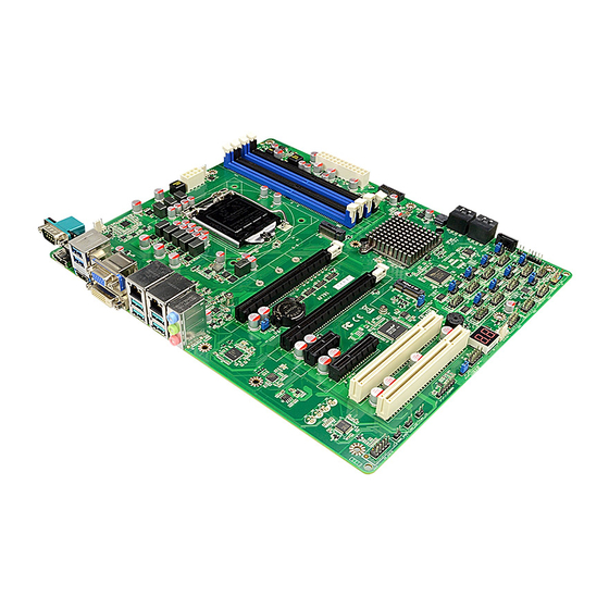
Page 6: Layout Diagram
2* RJ-45 LAN port 1*3-phone audio jack (Line-in, Line-out, MIC) Internal I/O Connectors & Headers: 1 *24-pin main power connector 1 *8-pin 12V power connector 1* CPUFAN connector & 2* SYSFAN connector 1* Front panel header ... - Page 7 Motherboard Internal Diagram SYSFAN1 CPUFAN Connector Connector ATX 12V Power Connector DDR4 DIMM Slot x 4 LGA 1151 *Rear IO CPU Socket Connector (Refer to Page-2) ATX Power Connector M.2 M-Key Slot (M2M) USB 3.1(Gen.1) Port Headers Intel Chipset PCI Express x16 Slot (*PCIE1) PCI Express x16 Slot (*PCIE2) PCI Express x1 Slot (PCIE3) M.2 E-key Slot...
- Page 8 Motherboard Jumper Position JBAT JP6 JP7 COPEN JP11 JP10 JAT_ATX JP12 Jumper Jumper Name Description COM1 Port Pin9 Function Select 4-pin Block JP12 COM2 Header Pin9 Function Select 4-pin Block COM3 Header Pin9 Function Select 4-pin Block COM4 Header Pin9 Function Select 4-pin Block JP10 COM5 Header Pin9 Function Select...
- Page 9 Connectors Connector Name COM1 RS232/422/485 Serial Port Connector Display Port Connector HDMI High-Definition Multimedia Interface Connector USB3 USB 3.1 (Gen.1) Port Connector X2 VGA Port Connector DVI1 DVI-D Port Connector UL1/UL2 Top:RJ-45 LAN Connector X2 Middle & Bottom: USB 3.1 (Gen.2) Port Connector X4 AUDIO Top: Line-in Connector...
-
Page 10: Chapter 2 Hardware Installation
Chapter 2 Hardware Installation 2-1 Jumper Setting JP1 (4-pin): COM1 Port Pin9 Function Select → COM1 Port 2-4 Closed: 3-4 Closed: 4-6 Closed: RI=RS232; RI= 5V; RI= 12V; JP12 (4-pin): COM2 Header Pin9 Function Select → JP12 COM2 Header 3-4 Closed: 2-4 Closed: 4-6 Closed: RI= 5V;... - Page 11 JP9 (4-pin): COM4 Header Pin9 Function Select → COM4 Header 3-4 Closed: 2-4 Closed: 4-6 Closed: RI= 5V; RI=RS232; RI= 12V. COM4 JP10 (4-pin): COM5 Header Pin9 Function Select → JP10 COM5 Header 3-4 Closed: 2-4 Closed: 4-6 Closed: RI= 5V; RI=RS232;...
- Page 12 JP5 (4-pin): COM8 Header Pin9 Function Select → COM8 Header COM8 3-4 Closed: 2-4 Closed: 4-6 Closed: RI= 5V; RI=RS232; RI= 12V. JP6 (4-pin): COM9 Header Pin9 Function Select → COM9 Header COM9 3-4 Closed: 2-4 Closed: 4-6 Closed: RI= 5V; RI=RS232;...
- Page 13 JBAT (3-pin): Clear CMOS RAM Settings → JBAT Clear CMOS 1-2 Open: Normal; JBAT 1-2 Closed: Clear CMOS. JP3 (3-pin): M2E (M.2 PCIE) Slot Power VCC Select → M2E Slot VCC 1-2 Closed:M2E Slot VCC= 3.3V; 2-3 Closed: M2E Slot VCC = 3.3VSB. JAT_ATX (3-pin): AT Mode /ATX Mode Select →...
- Page 14 COPEN (2-pin): Case Open Message Display Function → COPEN Case Open Detection COPEN Pin1 CASE OPEN Pin 1-2 Short: When Case open function pin short to GND, the Case open function was detected. When Used, needs to enter BIOS and enable ‘Case Open Detect’ function.
-
Page 15: Connectors And Headers
Connectors and Headers 2-2-1 Rear I/O Back Panel Connectors COM1 RS232/422/485 RJ-45 LAN Ports USB 3.1 (Gen.1) Serial Port Ports VGA Port Line-In Line-Out HDMI Port DVI-D Port USB3 .1 (Gen.2) DP Port Ports Icon Name Function Mainly for user to connect external MODEM or RS232/422/485 other devices that supports Serial Port... -
Page 16: Motherboard Internal Connectors
COM1 (9-pin Block): RS232/422/485 Port COM1 port can function as RS232/422/485 port. In normal settings COM1 functions as RS232 port. With compatible COM cable COM1 can function as RS422 or RS 485 port. User also needs to go to BIOS to set ‘Transmission Mode Select’ for COM1 (refer to Page-27) at first, before using specialized cable to connect different pins of this port. - Page 17 Figure1:20-pin power plug Figure 2:24-pin power plug (2) ATX12V (8-pin block): 12V Power Connector This is a new defined 8-pin connector that usually comes with ATX Power Supply that supports extra 12V voltage to maintain system power consumption. Without this connector might cause system unstable because the power supply can not provide sufficient current for system.
- Page 18 (4) SATA_RA1/DATA_RA2/5: SATAIII Port Connector These connectors are high-speed SATAIII ports that support 6 GB/s transfer rate. Pin No. Definition (5) M2M: M.2 M-Key Slot M2M M.2 M-Key slot supports compatible type 2242/2260/2280/22110 SATA or PCIE x4 SSD module. M2M Slot Installation Guide: 1.
- Page 19 2. Remove the screw post and nut fixed at 3. Lock the screw post into the location location MH4 by default (Skip step 2 & 3 corresponding to the length of the and go straight to Step 4 if you are going module.
-
Page 20: Header Pin Definition
2-2-3 Header Pin Definition (1) FP (9-pin): Front Panel Header Pin 1 (2) SPK_LED(7-pin): PWR LED Header & Speaker Header Pin 1 SPK_LED (3) FP_AUDIO (9-pin): Line-Out, MIC-In Header This header is connected to Front Panel Line-out, MIC connector with cable. FP_AUDIO Pin 1... - Page 21 (4) HDMI_SPDIF (2-pin): HDMI-SPDIF Out header HDMI_SPDIF Pin1 (5) LAN1_LED/ LAN2_LED (2-pin): LAN Status LED Header Pin1 LAN2_LED LAN1_LED (6) PS2KBMS (6-pin): PS/2 Keyboard & Mouse Header Pin1 PS2KBMS...
- Page 22 (7) GPIO (10-pin): GPIO Header Pin1 GPIO (8) SMBUS (5-pin): SM BUS Header VCC3 SMBUS SMBUS_ALERT- SMBUS_DATA SMBUS_CLK Pin 1 (9) USB1/USB2(9-pin): USB 2.0 Port Headers Pin 1 USB1 USB2...
- Page 23 (10) FP_USB (19-pin): USB 3.1(Gen.1) Port Header SSTX1+ SSTX1- SSTX2+ SSTX2- SSRX1+ SSRX2+ SSRX1- SSRX2- VBUS VBUS FP_USB Pin 1 (11) COM2/3/4/5/6/7/8/9/10 (9-pin): Serial Port Header : COM2 RS232/422/485 Serial Port; : COM3/4/5/6/7/8/9 RS232 Serial Port Header. *RS422 *RS485 Pin NO. RS232 (optional) (optional) Pin 1...
-
Page 24: Chapter 3 Introducing Bios
Chapter 3 Introducing BIOS Notice! The BIOS options in this manual are for reference only. Different configurations may lead to difference in BIOS screen and BIOS screens in manuals are usually the first BIOS version when the board is released and may be different from your purchased motherboard. Users are welcome to download the latest BIOS version form our official website. -
Page 25: Bios Menu Screen
3-2 BIOS Menu Screen The following diagram show a general BIOS menu screen: Menu Bar General Help Items Current Setting Value Menu Items Function Keys BIOS Menu Screen 3-3 Function Keys In the above BIOS Setup main menu of, you can see several options. We will explain these options step by step in the following pages of this chapter, but let us first see a short description of the function keys you may use here: ... -
Page 26: Getting Help
3-4 Getting Help Main Menu The on-line description of the highlighted setup function is displayed at the top right corner the screen. Status Page Setup Menu/Option Page Setup Menu Press 【F1】 to pop up a small help window that describes the appropriate keys to use and the possible selections for the highlighted item. -
Page 27: Advanced Menu
3-7 Advanced Menu CPU Configuration Press [Enter] to view current CPU configuration and make settings for the following sub-items: Hyper-Threading The optional settings: [Disabled]; [Enabled]. When set as [Disabled] only one thread per enabled core is enabled. [Enabled]: for Windows and Linux (OS optimized for Hyper-Threading Technology). - Page 28 SATA Mode Selection This item controls how SATA controller(s) operate. The optional settings are: [AHCI]; [RAID]. SATA1/SATA2/SATA3/SATA4/SATA5 Port The optional settings are: [Disabled]; [Enabled]. Use this item to enable or disable SATA port. Hot Plug Use this item to designate this port as Hot Pluggable. The optional settings are: [Disabled];...
- Page 29 *When set as [Enabled], user can make further settings in ‘CIRA Timeout’. CIRA Timeout OEM defined timeout for MPS connection to be established. The setting range is from [0] to [255]. [0]: use the default timeout value of 60 seconds; [255]: MEBx waits until the connection succeeds.
- Page 30 Press [Enter] to make settings for in the following sub-items: Non-UI Mode Resolution Use this item to set resolution for non-UI text mode. The optional settings are: [Auto]; [80x25]; [100x31]. UI Mode Resolution Use this item to set resolution for UI text mode. The optional settings are: [Auto];...
- Page 31 *This function is supported when ‘ERP Support’ is set as [Disabled]. USB S3/S4 Wake-up The optional settings are: [Enabled]; [Disabled]. Use this item to enable or disable USB wake-up from S3/S4 state. *This function is supported when ‘ERP Support’ is set as [Disabled]. USB S5 Power Use this item to enable or disable USB power after power shutdown.
- Page 32 This item support Emulate AT power function, MB power On/Off control by power supply. Use needs to select ‘AT or ATX Mode’ on MB jumper at first (refer to Page- 9, JAT_ATX jumper for ATX Mode & AT Mode Select). Case Open Detect Use this item to detect case has already open or not, show message in POST.
- Page 33 COM1 Console Redirection The optional settings are: [Disabled]; [Enabled]. When set as [Enabled], the following sub-items shall appear: Console Redirection Settings The settings specify how the host computer and the remote computer (which the user is using) will exchange data. Both computers should have the same or compatible settings.
- Page 34 Use this item to enable or disable extended terminal resolution. The optional settings: [Disabled]; [Enabled]. Putty KeyPad Use this item to select FunctionKey and KeyPad on Putty. The optional settings are: [VT100]; [Linux]; [XTERMR6]; [SCO]; [ESCN]; [VT400]. Legacy Console Redirection ...
- Page 35 Flow control can prevent data loss from buffer overflow. When sending data, if the receiving buffers are full, a “stop” signal can be sent to stop the data flow. Once the buffers are empty, a “start” signal can be sent to re-start the flow. Hardware flow control uses two wires to send start/stop signals.
- Page 36 The optional settings are: [Disabled]; [Enabled]. *When set as [Enabled], the following sub-items shall appear: Ipv4 PXE Support The optional settings are: [Disabled]; [Enabled]. Use this item to enable IPv4 PXE boot support. When set as [Disabled], IPv4 boot support will not be available. Ipv6 PXE Support The optional settings are: [Disabled];...
-
Page 37: Chipset Menu
3-8 Chipset Menu System Agent (SA) Configuration Press [Enter] to make settings for the following sub-items: VT-d The optional settings are: [Enabled]; [Disabled]. ► Memory Configuration Press [Enter] to view brief information for the working memory module. ► Graphics Configuration Press [Enter] to make further settings for Graphics Configuration. - Page 38 automatically enabled when selecting 2048MB aperture. To use this feature, please disable CSM Support. The optional settings are: [128MB]; [256MB]; [512MB]; [1024MB]; [2048MB]. DVMT Pre-allocated Use this item to select DVMT 5.0 Pre-Allocated (Fixed) Graphics Memory size used by the Internal Graphics Device. The optional settings are: [32M];...
-
Page 39: Security Menu
PCIE3 Slot/PCIE4 Slot Use this item to control respective PCI Express Root Port. The optional settings are: [Disabled]; [Enabled]. Speed The optional settings are: [Auto]; [Gen1]; [Gen2]. PCI Slot Use this item to control PCI slot. The optional settings are: [Disabled]; [Enabled]. M2M Slot Use this item to enable or disable M2E slot function. - Page 40 Secure Boot Press [Enter] to make customized secure settings: Secure Boot The optional settings are: [Disabled]; [Enabled]. Secure Boot feature is active if Secure Boot is enabled, Platform Key (PK) is enrolled and the system is in User mode. The mode change requires platform reset.
-
Page 41: Boot Menu
Secure Boot Variable/Size/Keys/Key Source Platform Key (PK)/Key Exchange Keys/Authorized Signature/Forbidden Signature/ Authorized TimeStamps/OS Recovery Signatures Use this item to enroll Factory Defaults or load the keys from a file with: 1. Public Key Certificate in: a) EFI_SIGNATURE_LIST b) EFI_ CERT_X509 (DER encoded) c) EFI_ CERT_RSA2048 (bin) d) EFI_ CERT_SHAXXX (bin) 2. -
Page 42: Save & Exit Menu
3-11 Save & Exit Menu Save Options Save Changes and Reset This item allows user to reset the system after saving the changes. Discard Changes and Reset This item allows user to reset the system without saving any changes. Default Options Restore Defaults Use this item to restore /load default values for all the setup options.