
Related Manuals for Pentair FLECK 5810 XTR2


Summary of Contents for Pentair FLECK 5810 XTR2
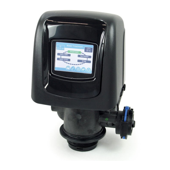
- Page 1 FLECK 5810 & 5812 XTR2 WATER SOFTENER OR FILTER CONTROL VALVE SERVICE MANUAL 5810 5812 waterpurification.pentair.com...
-
Page 2: Table Of Contents
TABLE OF CONTENTS IMPORTANT PLEASE READ: • The information, specifications and illustrations in this manual are OPERATING PARAMETERS ............2 based on the latest information available at the time of release. The INSTALLATION ................. 3 manufacturer reserves the right to make changes at any time without notice. -
Page 3: Installation
INSTALLATION Water Pressure 6. Soldering of joints near the drain port must be done prior to connecting the Drain Line Flow Control fitting (DLFC). A minimum of 20 psi (1.4 bar) of water pressure is required for Leave at least 6" (15 cm) between the DLFC and solder the regeneration valve to operate effectively. - Page 4 INSTALLATION continued Typical Residential System Plumbing Bath Tub Lavatory Toilet Kitchen Outside Outside Faucet Faucet Hot Water Grounding Soft Water Outlet Strap Hard Water Bypass Drain Line Water Heater Brine Tank Over ow Drain (Optional) Laundry Tubs Pump Meter Softener Floor Drain Figure 3 Softened Water Flow 4 •...
-
Page 5: Start-Up Instructions/Flushing & Conditioning
START-UP INSTRUCTIONS/ SYSTEM DISINFECTION FLUSHING & CONDITIONING Disinfection of Water Softeners The materials of construction of the modern water softener The water softener should be installed with the inlet, will not support bacterial growth, nor will these materials outlet, and drain connections made in accordance with the manufacturer’s recommendations, and to meet applicable contaminate a water supply. -
Page 6: Touchscreen Control Quick Start
TOUCHSCREEN CONTROL QUICK START Using the keypad, type the name of the water treatment The XTR2 control was designed to be easy to set up and begin professional or company that the homeowner may call for using right out of the box. The following simple procedure can system service (optional). - Page 7 TOUCHSCREEN CONTROL QUICK START continued 6. Start a regeneration by pressing the Regeneration button 5. After pressing , the Home screen (Figure 8) appears. . The Regeneration screen appears (Figure 10). Next Scheduled Regeneration Day and Time Current Cycle Step Regeneration Cycle Wheel Figure 10 Regeneration Screen...
-
Page 8: Touchscreen Control Features
TOUCHSCREEN CONTROL FEATURES Assistance Features of the XTR2 Touchscreen Control • Displays a name and phone number to call for unit • Full-featured easy to use graphical touchscreen interface service. for programming, servicing, and diagnostics. • Non-linear programming no longer requires cycling USB Connect through every parameter when programming/servicing. - Page 9 TOUCHSCREEN CONTROL FEATURES • Day and Time: Displays the currently programmed day of the week and time. This button will flash if the control has continued been reset. Screen Features Regeneration Regenerate the system on demand by pressing the Home Screen Regeneration button on the home screen.
- Page 10 TOUCHSCREEN CONTROL FEATURES User Assistance continued Settings The Assistance screen displays the name and phone number that the homeowner may call for service of the unit. Press the The Settings screen allows you to change basic control settings Assistance button from the Master Settings or Home including time of regeneration and water hardness.
- Page 11 TOUCHSCREEN CONTROL FEATURES continued Press the screen navigation arrow at the top right of the screen The Password screen displays a numeric keypad. to navigate to the secondary Master Settings screen. Figure 19 Secondary Master Settings Screen Figure 17 Password Screen •...
-
Page 12: Master Settings Programming
TOUCHSCREEN CONTROL FEATURES MASTER SETTINGS PROGRAMMING continued Improperly adjusting master settings may cause Remote Regeneration Screen CAUTION the system to operate incorrectly. Before entering master settings please contact your professional From the secondary Master Settings screen (Figure 19) press water dealer. the remote regen button to display the Remote Regen screen. - Page 13 MASTER SETTINGS PROGRAMMING continued The reserve should be set to ensure that the system delivers treated water between the time the system capacity is depleted Valve Screen and the actual regeneration time. Reserves can be set at a Fixed Volume, Fixed Percentage of capacity, a Variable Reserve From the main Master Settings screen (Figure 18) press the based on the previous calendar day's water usage, or a Weekly valve button to display the Valve screen.
- Page 14 MASTER SETTINGS PROGRAMMING Meter Screen continued • regen flow: Contains settings for the type of regenerant From the main Master Settings screen (Figure 18) press the flow to be used in the valve. Changes to this setting meter button to display the Meter screen. affects the cycle steps displayed in the Regeneration Cycle Wheel on the Home screen.
- Page 15 MASTER SETTINGS PROGRAMMING Diagnostics continued Settings Review The control records and displays a variety of diagnostic data to assist with troubleshooting performance issues and fine-tuning From the main Master Settings screen (Figure 18) press the system efficiency. Press the Diagnostics button from the settings review button to display the Settings Review screens, Master Settings or Home screens to view the Diagnostic...
- Page 16 USB Connection for Field Programming Parameter Description The XTR2 features a USB port that allows you to connect a PC Flow Rate Displays the current flow rate. to the control for field programming and diagnostic parameter Peak Flow Displays maximum flow rate of water along download.
-
Page 17: Master Reset
MASTER RESET If power fails during a regeneration cycle, the Press the button while in the Master Settings main screen CAUTION valve will remain in its current position until power (Figure 18) to display the Reset screen. is restored. The valve system should include all required safety components to prevent overflows resulting from a power failure during regeneration. -
Page 18: Master Settings Reference Chart
MASTER SETTINGS REFERENCE CHART Before entering Master Settings, please contact your local professional water dealer. CAUTION Screen Name Parameters Values Notes Format Language English, French, Changes the language to display screen text and button labels in the control (available with international German, Italian, version of control only). -
Page 19: Troubleshooting
TROUBLESHOOTING Problem Cause Correction Valve constantly Error in programming has caused Disconnect the motor from the control circuit board (see "WIRING DIAGRAM" on regenerates a regeneration loop condition in the page "WIRING DIAGRAM" on page 33 for location on circuit board). A Motor Stall control. -
Page 20: 5810 Control Valve Assembly
5810 CONTROL VALVE ASSEMBLY Item No. Part No. Description 1 ....1 ..581008-001 ... 5810, SOF, DNF, M14, XTR2, 12-DC, CW 00-, .12, LES, NA2, 1600, SOFT ..581008-002 ... 5810, SOF, UPF, M14, XTR2, 12-DC, CW 00-, .12, LES, NA2, 1600, SOFT .. - Page 21 5810 CONTROL VALVE ASSEMBLY Item No. Part No. Description 1 ....1 ..61961 ....Kit, Mounting, 5810/5812 2 ....1 ..61956-01 ....Kit, Piston, Seal, and Spacer, 5810, Downflow ..61956-02 ....Kit, Piston, Seal, and Spacer, 5810, Upflow ..
- Page 22 5812 CONTROL VALVE ASSEMBLY Item No. Part No. Description 1....1 ..61961 ....Kit, Mounting, 5810/5812 2....1 ..61960-01 ....Kit, Piston, Seal, and Spacer, 5812, Downflow ..61960-02 ....Kit, Piston, Seal, and Spacer, 5812, Upflow ..61960-03 ....Kit, Piston, Seal, and Spacer, 5812, Filter 3....1 ..
-
Page 23: 5810/5812 Valve Accessories
5810/5812 VALVE ACCESSORIES DLFC - 5810 ONLY 61455-00 .....DLFC, ¾", Elbow, NPT, Blank, Covers For 0.6-7.0 GPM Washers 43261 ......Cover, 5800 61456-00 .....DLFC Assy, 1", Straight, NPT, 43715 ......Cover, 5800, Lower For 0.8 - 25 GPM Washers 61994 ......Cover Assy, Environmental 5810/5812 62088-00 .....DLFC Assy, 1", Straight, NPT, Gray Blank,For 8.0 - 25 GPM Washers... -
Page 24: 5810/5812 Valve Assemblies
5810/5812 VALVE ASSEMBLIES BLFC 61450-00 .....BLFC, 3/8", Blank 61450-12 .....BLFC, 3/8", 0.125 GPM 61450-25 .....BLFC, 3/8", 0.25 GPM 61450-50 .....BLFC, 3/8", 0.50 GPM 61450-100 ....BLFC, 3/8", 1.0 GPM 61451-00 .....BLFC, 1/2", Blank 61451-12 .....BLFC, 1/2", 0.125 GPM 61451-25 .....BLFC, 1/2", 0.25 GPM BLFC (3/8") BLFC (1/2") 61451-50 .....BLFC, 1/2", 0.50 GPM... -
Page 25: Safety Brine Valve
SAFETY BRINE VALVE 42112 Rev A Item No. Part No. Description 1....1 ..19645 ....Body, Safety Brine Valve, 2310 2....1 ..19803 ....Safety Brine Valve Assy 3....1 ..19804 ....Screw, Sckt Hd, Set, 10-24 x 0.75 4....1 ..19805 ....Nut, Hex, 10-24, Nylon Black 5....1 .. -
Page 26: Water Conditioner Flow Diagrams
WATER CONDITIONER FLOW DIAGRAMS 2. BACKWASH POSITION 5810 Upflow BRINE CAM 1. SERVICE POSITION BRINE VALVE DRAIN BRINE LINE BRINE CAM INLET BRINE VALVE DRAIN BRINE LINE INLET AIR CHECK OUTLET AIR CHECK BRINE TANK RESIN TANK 4. RAPID RINSE POSITION BRINE TANK RESIN TANK BRINE CAM... - Page 27 WATER CONDITIONER FLOW DIAGRAMS 3. BRINE/SLOW RINSE POSITION continued 5810 Downflow 1. SERVICE POSITION BRINE LINE INLET BRINE CAM BRINE VALVE DRAIN BRINE LINE INLET OUTLET AIR CHECK 4. RAPID RINSE POSITION BRINE CAM BRINE VALVE BRINE TANK RESIN TANK DRAIN BRINE LINE 2.
- Page 28 WATER CONDITIONER FLOW DIAGRAMS 3. BACKWASH POSITION 5812 Upflow 1. SERVICE POSITION 4. RAPID RINSE POSITION DRAIN 2. BRINE/SLOW RINSE POSITION BRINE LINE INLET 5. BRINE TANK REFILL POSITION BRINE LINE INLET BRINE TANK RESIN TANK 28 • FLECK 5810 & 5812 XTR2 Service Manual...
- Page 29 WATER CONDITIONER FLOW DIAGRAMS 3. BRINE/SLOW RINSE POSITION continued DRAIN BRINE CAM 5812 Downflow BRINE VALVE BRINE LINE 1. SERVICE POSITION INLET BRINE CAM DRAIN BRINE VALVE BRINE LINE OUTLET AIR CHECK INLET BRINE TANK RESIN TANK AIR CHECK 4. RAPID RINSE POSITION BRINE TANK RESIN TANK DRAIN...
-
Page 30: 5810 Dimensional Drawings
5810 DIMENSIONAL DRAWINGS 71.50 2.815 287.4 11.32 5.75 47.8 1.88 29.6 1.17 140.1 120.3 5.52 4.74 122.4 4.82 91.4 3.60 182.9 7.20 61500-5810LNE REV A 30 • FLECK 5810 & 5812 XTR2 Service Manual... -
Page 31: 5812 Dimensional Drawings
5812 DIMENSIONAL DRAWINGS 5812 2.5" BASE 71.50 2.815 12.0 171.2 6.74 5.51 65.4 2.57 29.6 1.17 91.4 140.08 120.3 3.60 5.515 4.74 182.9 7.20 5812 4" BASE 71.50 2.815 12.0 170.31 6.71 140.1 5.52 65.5 2.58 36.8 1.45 91.4 3.60 140.1 120.3 5.51... -
Page 32: Transformer Port Location
TRANSFORMER PORT LOCATION Transformer port location (plugging in transformer) When looking at valve from front, reach around back under cover on right hand side. Transformer port is located just past the cover’s snap feature. 44288 REV A 32 • FLECK 5810 & 5812 XTR2 Service Manual... -
Page 33: Wiring Diagram
WIRING DIAGRAM NOTE: The reset switch discharges the super capacitor 44218 Rev A when power is removed from the control. The super capacitor retains the current time of day in the event of a power failure. Pressing the reset switch on the circuit board while power is applied to the control will have no effect on the control or stored settings. -
Page 34: Injector Flow Data
INJECTOR FLOW DATA TR18755 REV B 34 • FLECK 5810 & 5812 XTR2 Service Manual... - Page 35 FLECK 5810 & 5812 XTR2 Service Manual • 35...
- Page 36 P: 262.238.4400 | WATERPURIFICATION.PENTAIR.COM CUSTOMER CARE: 800.279.9404 | tech-support pentair.com For a detailed list of where Pentair trademarks are registered, please visit waterpurification.pentair.com. § Pentair trademarks and logos are owned by Pentair plc or its affiliates. Third party registered and unregistered trademarks and logos are the property of their respective owners.