Table of Contents
Advertisement
Advertisement
Table of Contents

Related Manuals for ASROCK X370 KILLER SLI/AC


Summary of Contents for ASROCK X370 KILLER SLI/AC
- Page 2 (including damages for loss of profits, loss of business, loss of data, interruption of business and the like), even if ASRock has been advised of the possibility of such damages arising from any defect or error in the documentation or product.
- Page 3 If you require assistance please call ASRock Tel : +886-2-28965588 ext.123 (Standard International call charges apply) The terms HDMI™...
-
Page 4: Table Of Contents
Contents Chapter 1 Introduction Package Contents Specifications Motherboard Layout I/O Panel WiFi-802.11ac Module and ASRock WiFi 2.4/5 GHz Antenna (for X370 Killer SLI/ac only) Chapter 2 Installation Installing the CPU Installing the CPU Fan and Heatsink Installing Memory Modules (DIMM) - Page 5 A-Tuning 3.2.1 Installing A-Tuning 3.2.2 Using A-Tuning ASRock Live Update & APP Shop 3.3.1 UI Overview 3.3.2 Apps 3.3.3 BIOS & Drivers 3.3.4 Setting ASRock RGB LED Chapter 4 UEFI SETUP UTILITY Introduction 4.1.1 UEFI Menu Bar 4.1.2 Navigation Keys...
- Page 6 Tools Hardware Health Event Monitoring Screen Security Screen Boot Screen Exit Screen...
-
Page 7: Chapter 1 Introduction
If you require technical support related to this mother- board, please visit our website for specific information about the model you are using. You may find the latest VGA cards and CPU support list on ASRock’s website as well. ASRock website http://www.asrock.com. -
Page 8: Specifications
• AMD 7 Gen A-Series APUs support DDR4 2133 ECC & non-ECC, un-buffered memory* * Please refer to Memory Support List on ASRock’s website for more information. (http://www.asrock.com/) * Please refer to page 25 for DDR4 UDIMM maximum frequency support. - Page 9 X370 Killer SLI/ac / X370 Killer SLI Graphics • Integrated AMD Radeon R7/R5 Series Graphics in A-series • DirectX 12, Pixel Shader 5.0 • Max. shared memory 2GB • Supports HDMI with max. resolution up to 4K x 2K (4096x2160) @ 24Hz / (3840x2160) @ 30Hz • Supports Auto Lip Sync, Deep Color (12bpc), xvYCC and...
- Page 10 M.2 SATA3 6.0 Gb/s module and M.2 PCI Express module up to Gen2 x2 (10 Gb/s)* * Supports NVMe SSD as boot disks * Supports ASRock U.2 Kit Connector • 1 x COM Port Header • 1 x TPM Header • 1 x Power LED and Speaker Header...
- Page 11 • Fan Multi-Speed Control: CPU, CPU Optional/Water Pump, Chassis, Chassis Optional/Water Pump Fans • Voltage monitoring: +12V, +5V, +3.3V, CPU Vcore, VCORE_ NB, DRAM, PCH 1.05V, +1.8V, VDDP • Microsoft® Windows® 10 64-bit * For the updated Windows® 10 driver, please visit ASRock’s website for details: http://www.asrock.com...
- Page 12 • ErP/EuP ready (ErP/EuP ready power supply is required) * For detailed product information, please visit our website: http://www.asrock.com Please realize that there is a certain risk involved with overclocking, including adjusting the setting in the BIOS, applying Untied Overclocking Technology, or using third-party overclocking tools.
-
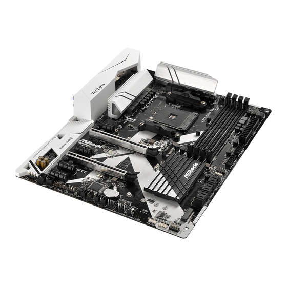
Page 13: Motherboard Layout
X370 Killer SLI/ac / X370 Killer SLI 1.3 Motherboard Layout CPU_OPT/W_PUMP CPU_FAN1 USB 3.0 T: USB1 B: USB2 USB 3.0 T: USB3 B: USB4 USB 3.0 T: USB3_TA_1 B: USB3_TC_1 USB 3.0 Top: T: USB5 RJ-45 B: USB6 NUT1 PCIE1... - Page 14 No. Description ATX 12V Power Connector (ATX12V1) CPU Fan Connector (CPU_FAN1) CPU Fan / Waterpump Fan Connector (CPU_OPT/W_PUMP) 2 x 288-pin DDR4 DIMM Slots (DDR4_A1, DDR4_B1) 2 x 288-pin DDR4 DIMM Slots (DDR4_A2, DDR4_B2) ATX Power Connector (ATXPWR1) USB 3.0 Header (USB3_9_10) USB 3.0 Header (USB3_7_8) AMD LED Fan USB Header (USB_5) AMD Fan LED Header (AMD_FAN_LED1)
-
Page 15: I/O Panel
X370 Killer SLI/ac / X370 Killer SLI 1.4 I/O Panel No. Description No. Description PS/2 Mouse Port USB 3.0 Ports (USB3_5_6) LAN RJ-45 Port* USB 3.0 Type-A Port (USB3_TA_1) Central / Bass (Orange) USB 3.0 Type-C Port (USB3_TC_1) Rear Speaker (Black) USB 3.0 Ports (USB3_3_4) - Page 16 ** If you use a 2-channel speaker, please connect the speaker’s plug into “Front Speaker Jack”. See the table below for connection details in accordance with the type of speaker you use. Audio Output Front Speaker Rear Speaker Central / Bass Line In Channels (No.
-
Page 17: Wifi-802.11Ac Module And Asrock Wifi 2.4/5 Ghz Antenna (For X370 Killer Sli/Ac Only)
X370 Killer SLI/ac / X370 Killer SLI 1.5 WiFi-802.11ac Module and ASRock WiFi 2.4/5 GHz Antenna (for X370 Killer SLI/ac only) WiFi-802.11ac + BT Module This motherboard comes with an exclusive WiFi 802.11 a/b/g/n/ac + BT v4.0 module (pre-installed on the rear I/O panel) that offers support for WiFi 802.11 a/b/ g/n/ac connectivity standards and Bluetooth v4.0. - Page 18 WiFi Antennas Installation Guide Step 1 Prepare the WiFi 2.4/5 GHz Antennas that come with the package. Step 2 Connect the two WiFi 2.4/5 GHz Antennas to the antenna connectors. Turn the antenna clock- wise until it is securely connected. Step 3 Set the WiFi 2.4/5 GHz Antenna as shown in the illustration.
-
Page 19: Chapter 2 Installation
X370 Killer SLI/ac / X370 Killer SLI Chapter 2 Installation This is a ATX form factor motherboard. Before you install the motherboard, study the configuration of your chassis to ensure that the motherboard fits into it. Pre-installation Precautions Take note of the following precautions before you install motherboard components or change any motherboard settings. -
Page 20: Installing The Cpu
2.1 Installing the CPU Unplug all power cables before installing the CPU. - Page 21 X370 Killer SLI/ac / X370 Killer SLI...
-
Page 22: Installing The Cpu Fan And Heatsink
2.2 Installing the CPU Fan and Heatsink After you install the CPU into this motherboard, it is necessary to install a larger heatsink and cooling fan to dissipate heat. You also need to spray thermal grease between the CPU and the heatsink to improve heat dissipation. Make sure that the CPU and the heatsink are securely fastened and in good contact with each other. - Page 23 X370 Killer SLI/ac / X370 Killer SLI...
- Page 24 Installing the AM4 Box Cooler SR2...
- Page 25 X370 Killer SLI/ac / X370 Killer SLI...
- Page 26 4-pin FAN cable RGB LED Cable +12V *The diagram shown here are for reference only. Please refer to page 33 for the orientation of AMD Fan LED Header (AMD_FAN_LED1).
- Page 27 X370 Killer SLI/ac / X370 Killer SLI Installing the AM4 Box Cooler SR3...
- Page 29 X370 Killer SLI/ac / X370 Killer SLI...
- Page 30 +12V Please note that only one cable should be used at a time in this step. If you select AMD_FAN_LED1, please install ASRock utility "ASRock RGB LED". If you select USB connector, please install AMD utility "SR3 Settings Software". *The diagram shown here are for reference only. Please refer to page 33 for the orientation of AMD Fan...
-
Page 31: Installing Memory Modules (Dimm)
X370 Killer SLI/ac / X370 Killer SLI 2.3 Installing Memory Modules (DIMM) This motherboard provides four 288-pin DDR4 (Double Data Rate 4) DIMM slots, and supports Dual Channel Memory Technology. 1. For dual channel configuration, you always need to install identical (the same brand, speed, size and chip-type) DDR4 DIMM pairs. - Page 32 The DIMM only fits in one correct orientation. It will cause permanent damage to the motherboard and the DIMM if you force the DIMM into the slot at incorrect orientation.
-
Page 33: Expansion Slots (Pci Express Slots)
X370 Killer SLI/ac / X370 Killer SLI 2.4 Expansion Slots (PCI Express Slots) There are 6 PCI Express slots on the motherboard. Before installing an expansion card, please make sure that the power supply is switched off or the power cord is unplugged. Please read the documentation of the expansion card and make necessary hardware settings for the card before you start the installation. -
Page 34: Jumpers Setup
2.5 Jumpers Setup The illustration shows how jumpers are setup. When the jumper cap is placed on the pins, the jumper is “Short”. If no jumper cap is placed on the pins, the jumper is “Open”. The illustration shows a 3-pin jumper whose pin1 and pin2 are “Short” when a jumper cap is placed on these 2 pins. -
Page 35: Onboard Headers And Connectors
X370 Killer SLI/ac / X370 Killer SLI 2.6 Onboard Headers and Connectors Onboard headers and connectors are NOT jumpers. Do NOT place jumper caps over these headers and connectors. Placing jumper caps over the headers and connectors will cause permanent damage to the motherboard. - Page 36 Power LED and Speaker Please connect the SPEAKER DUMMY Header chassis power LED and DUMMY (7-pin SPK_PLED1) the chassis speaker to this (see p.7, No. 23) header. PLED+ PLED+ PLED- Serial ATA3 Connectors These six SATA3 (SATA3_1_2: connectors support SATA see p.7, No.
- Page 37 X370 Killer SLI/ac / X370 Killer SLI USB 3.0 Header Besides four USB 3.0 ports Vbus Vbus Vbus IntA_PB_SSRX- (19-pin USB3_7_8) on the I/O panel, there IntA_PB_SSRX+ IntA_PA_SSRX- IntA_PA_SSRX+ (see p.7, No. 8) are two headers on this IntA_PB_SSTX- IntA_PA_SSTX-...
- Page 38 Chassis Optional/Water This motherboard Pump Fan Connector provides two 4-Pin water FAN_SPEED_CONTROL (4-pin CHA_FAN3/W_ cooling chassis fan CHA_FAN_SPEED FAN_VOLTAGE PUMP) connectors. If you plan to (see p.7, No. 19) connect a 3-Pin chassis water cooler fan, please connect it to Pin 1-3. CPU Fan Connectors This motherboard pro- FAN_SPEED_CONTROL...
- Page 39 X370 Killer SLI/ac / X370 Killer SLI Serial Port Header This COM1 header RRXD1 DDTR#1 DDSR#1 (9-pin COM1) supports a serial port CCTS#1 (see p.7, No. 25) module. RRI#1 RRTS#1 TTXD1 DDCD#1 TPM Header This connector supports Trusted (17-pin TPMS1) Platform Module (TPM) system, (see p.7, No.
-
Page 40: Sli Tm And Quad Sli Tm Operation Guide
2.7 SLI and Quad SLI Operation Guide ® This motherboard supports NVIDIA and Quad SLI (Scalable Link Interface) technology that allows you to install up to two identical PCI Express x16 graphics cards. Requirements ® 1. You should only use identical SLI -ready graphics cards that are NVIDIA certified. - Page 41 X370 Killer SLI/ac / X370 Killer SLI Step 3 Align and insert the ASRock SLI_HB_ Bridge_2S Card to the goldfingers on each graphics card. Make sure the ASRock SLI_ HB_Bridge_2S Card is firmly in place. SLI_HB_Bridge_2S Car d ASRock SLI_HB_Bridge_2S Card...
-
Page 42: Driver Installation And Setup
2.7.2 Driver Installation and Setup Install the graphics card drivers to your system. After that, you can enable the ® Multi-Graphics Processing Unit (GPU) in the NVIDIA nView system tray utility. Please follow the below procedures to enable the multi-GPU. For SLI and Quad SLI mode... -
Page 43: Tm Tm
X370 Killer SLI/ac / X370 Killer SLI 2.8 CrossFireX and Quad CrossFireX Operation Guide This motherboard supports CrossFireX and Quad CrossFireX that allows you to install up to two identical PCI Express x16 graphics cards. 1. You should only use identical CrossFireX -ready graphics cards that are AMD certified. - Page 44 Step 3 Connect a VGA cable or a DVI cable to the monitor connector or the DVI connec- tor of the graphics card that is inserted to PCIE2 slot.
-
Page 45: Driver Installation And Setup
X370 Killer SLI/ac / X370 Killer SLI 2.8.2 Driver Installation and Setup Step 1 Power on your computer and boot into OS. Step 2 Remove the AMD drivers if you have any VGA drivers installed in your system. The Catalyst Uninstaller is an optional download. We recommend using this utility to un- install any previously installed Catalyst drivers prior to installation. -
Page 46: M.2_Ssd (Ngff) Module Installation Guide
2.9 M.2_SSD (NGFF) Module Installation Guide The M.2, also known as the Next Generation Form Factor (NGFF), is a small size and versatile card edge connector that aims to replace mPCIe and mSATA. The Ultra M.2 Socket (M2_1) supports SATA3 6.0 Gb/s module and M.2 PCI Express module up to Gen3 x4 (32 Gb/s) (with Ryzen CPU) or Gen3 x2 (16 Gb/s) (with A-Series APU). - Page 47 X370 Killer SLI/ac / X370 Killer SLI Step 3 Move the standoff based on the module type and length. The standoff is placed at the nut location D by default. Skip Step 3 and 4 and go straight to Step 5 if you are going to use the default nut.
- Page 48 SATA V-Color 120G V-Color SATA V-Color 240G SanDisk SATA Sandisk Z400s-SD8SNAT-128G-1122 Transcend SATA Transcend TS64GMTS400-64GB SATA WD BLUE WDS100T1B0B-00AS40 SATA WD GREEN WDS240G1G0B-00RC30 For the latest updates of M.2_SSD (NFGG) module support list, please visit our website for details: http://www.asrock.com...
- Page 49 X370 Killer SLI/ac / X370 Killer SLI M.2_SSD (NGFF) Module Support List (M2_2) Vendor Interface Intel PCIe INTEL 6000P-SSDPEKKF256G7 (nvme) Intel PCIe INTEL 6000P-SSDPEKKF512G7 (nvme) Kingston PCIe Kingston SHPM2280P2 / 240G (Gen2 x4) Samsung PCIe Samsung XP941-MZHPU512HCGL(Gen2x4) SanDisk PCIe SanDisk-SD6PP4M-128G( Gen2 x2)
-
Page 50: Chapter 3 Software And Utilities Operation
Chapter 3 Software and Utilities Operation 3.1 Installing Drivers The Support CD that comes with the motherboard contains necessary drivers and useful utilities that enhance the motherboard’s features. Running The Support CD To begin using the support CD, insert the CD into your CD-ROM drive. The CD automatically displays the Main Menu if “AUTORUN”... -
Page 51: A-Tuning
X370 Killer SLI/ac / X370 Killer SLI 3.2 A-Tuning A-Tuning is ASRock’s multi purpose software suite with a new interface, more new features and improved utilities. 3.2.1 Installing A-Tuning A-Tuning can be downloaded from ASRock Live Update & APP Shop. After the installation, you will find the icon “A-Tuning“... - Page 52 OC Tweaker Configurations for overclocking the system. System Info View information about the system. *The System Browser tab may not appear for certain models.
- Page 53 Configure up to five different fan speeds using the graph. The fans will automatically shift to the next speed level when the assigned temperature is met. Settings Configure ASRock A-Tuning. Click to select "Auto run at Windows Startup" if you want A-Tuning to be launched when you start up the Windows operating system.
-
Page 54: Asrock Live Update & App Shop
Double-click on your desktop to access ASRock Live Update & APP Shop utility. *You need to be connected to the Internet to download apps from the ASRock Live Update & APP Shop. 3.3.1 UI Overview Category Panel Hot News... -
Page 55: Apps
X370 Killer SLI/ac / X370 Killer SLI 3.3.2 Apps When the "Apps" tab is selected, you will see all the available apps on screen for you to download. Installing an App Step 1 Find the app you want to install. - Page 56 Step 3 If you want to install the app, click on the red icon to start downloading. Step 4 When installation completes, you can find the green "Installed" icon appears on the upper right corner. To uninstall it, simply click on the trash can icon *The trash icon may not appear for certain apps.
- Page 57 X370 Killer SLI/ac / X370 Killer SLI Upgrading an App You can only upgrade the apps you have already installed. When there is an available new version for your app, you will find the mark of "New Version" appears below the installed app icon.
-
Page 58: Bios & Drivers
3.3.3 BIOS & Drivers Installing BIOS or Drivers When the "BIOS & Drivers" tab is selected, you will see a list of recommended or critical updates for the BIOS or drivers. Please update them all soon. Step 1 Please check the item information before update. Click on to see more details. -
Page 59: Setting
X370 Killer SLI/ac / X370 Killer SLI 3.3.4 Setting In the "Setting" page, you can change the language, select the server location, and determine if you want to automatically run the ASRock Live Update & APP Shop on Windows startup. -
Page 60: Asrock Rgb Led
3.4 ASRock RGB LED ASRock RGB LED is a lighting control utility specifically designed for unique individuals with sophisticated tastes to build their own stylish colorful lighting system. Simply by connecting the LED strip, you can customize various lighting schemes and patterns, including Static, Breathing, Strobe, Cycling, Music, Wave and more. - Page 61 ASRock RGB LED Utility Now you can adjust the RGB LED color through the ASRock RGB LED utility. Download this utility from the ASRock Live Update & APP Shop and start coloring your PC style your way! Drag the tab to customize your preference.
-
Page 62: Chapter 4 Uefi Setup Utility
Chapter 4 UEFI SETUP UTILITY 4.1 Introduction This section explains how to use the UEFI SETUP UTILITY to configure your system. You may run the UEFI SETUP UTILITY by pressing <F2> or <Del> right after you power on the computer, otherwise, the Power-On-Self-Test (POST) will continue with its test routines. -
Page 63: Navigation Keys
X370 Killer SLI/ac / X370 Killer SLI 4.1.2 Navigation Keys Use < > key or < > key to choose among the selections on the menu bar, and use < > key or < > key to move the cursor up or down to select items, then press <Enter>... -
Page 64: Main Screen
4.2 Main Screen When you enter the UEFI SETUP UTILITY, the Main screen will appear and display the system overview. -
Page 65: Oc Tweaker Screen
X370 Killer SLI/ac / X370 Killer SLI 4.3 OC Tweaker Screen In the OC Tweaker screen, you can set up overclocking features. Because the UEFI software is constantly being updated, the following UEFI setup screens and descriptions are for reference purpose only, and they may not exactly match what you see on your screen. -
Page 66: Advanced Screen
4.4 Advanced Screen In this section, you may set the configurations for the following items: CPU Configuration, North Bridge Configuration, South Bridge Configuration, Storage- Configuration, Super IO Configuration, ACPI Configuration, USB Configuration and Trusted Computing. Setting wrong values in this section may cause the system to malfunction. UEFI Configuration Active Page on Entry Select the default page when entering the UEFI setup utility. -
Page 67: Cpu Configuration
X370 Killer SLI/ac / X370 Killer SLI 4.4.1 CPU Configuration Cool 'n' Quiet Use this item to enable or disable AMD’s Cool ‘n’ Quiet technology. The default value is [Enabled]. Configuration options: [Enabled] and [Disabled]. If you install ® Windows OS and want to enable this function, please set this item to [Enabled]. -
Page 68: North Bridge Configuration
4.4.2 North Bridge Configuration IOMMU Use this to enable or disable IOMMU. The default value of this feature is [Disabled]. Share Memory Configure the size of memory that is allocated to the integrated graphics processor when the system boots up. -
Page 69: South Bridge Configuration
X370 Killer SLI/ac / X370 Killer SLI 4.4.3 South Bridge Configuration Onboard HD Audio Enable/disable onboard HD audio. Set to Auto to enable onboard HD audio and automatically disable it when a sound card is installed. Front Panel Enable/disable front panel HD audio. -
Page 70: Storage Configuration
4.4.4 Storage Configuration SATA Controller(s) Enable/disable the SATA controllers. SATA Mode AHCI: Supports new features that improve performance. RAID: Combine multiple disk drives into a logical unit. -
Page 71: Super Io Configuration
X370 Killer SLI/ac / X370 Killer SLI 4.4.5 Super IO Configuration Serial Port Enable or disable the Serial port. Serial Port Address Select the address of the Serial port. -
Page 72: Acpi Configuration
4.4.6 ACPI Configuration Suspend to RAM It is recommended to select auto for ACPI S3 power saving. HPET In SB Enable the High Precision Event Timer for better performance and to pass WHQL tests. PS/2 Keyboard Power On Allow the system to be waked up by a PS/2 Keyboard. PCIE Devices Power On Allow the system to be waked up by a PCIE device and enable wake on LAN. -
Page 73: Usb Configuration
X370 Killer SLI/ac / X370 Killer SLI 4.4.7 USB Configuration USB Controller Enable or disable all the USB ports. Legacy USB Support Enable or disable Legacy OS Support for USB 2.0 devices. If you encounter USB compatibility issues it is recommended to disable legacy USB support. Select UEFI Setup Only to support USB devices under the UEFI setup and Windows/Linux operating systems only. -
Page 74: Trusted Computing
4.4.8 Trusted Computing Security Device Support Enable to activate Trusted Platform Module (TPM) security for your hard disk drives. - Page 75 X370 Killer SLI/ac / X370 Killer SLI 4.5 Tools RGB LED ASRock RGB LED allows you to adjust the RGB LED color to your liking. Easy RAID Installer Easy RAID Installer helps you to copy the RAID driver from the support CD to your USB storage device.
- Page 76 Save UEFI files in your USB storage device and run Instant Flash to update your UEFI. Internet Flash - DHCP (Auto IP), Auto ASRock Internet Flash downloads and updates the latest UEFI firmware version from our servers for you. Please setup network configuration before using Internet Flash.
- Page 77 X370 Killer SLI/ac / X370 Killer SLI 4.6 Hardware Health Event Monitoring Screen This section allows you to monitor the status of the hardware on your system, including the parameters of the CPU temperature, motherboard temperature, fan speed and voltage.
- Page 78 Chassis Fan 1 Setting Select a fan mode for Chassis Fan 1, or choose Customize to set 5 CPU temperatures and assign a respective fan speed for each temperature. Chassis Fan 1 Temp Source Select a fan temperature source for Chassis Fan 1. Chassis Fan 2 Setting Select a fan mode for Chassis Fan 2, or choose Customize to set 5 CPU temperatures and assign a respective fan speed for each temperature.
- Page 79 X370 Killer SLI/ac / X370 Killer SLI 4.7 Security Screen In this section you may set or change the supervisor/user password for the system. You may also clear the user password. Supervisor Password Set or change the password for the administrator account. Only the administrator has authority to change the settings in the UEFI Setup Utility.
- Page 80 4.8 Boot Screen This section displays the available devices on your system for you to configure the boot settings and the boot priority. Fast Boot Fast Boot minimizes your computer's boot time. In fast mode you may not boot from an USB storage device. Boot From Onboard LAN Allow the system to be waked up by the onboard LAN.
- Page 81 X370 Killer SLI/ac / X370 Killer SLI AddOn ROM Display Enable AddOn ROM Display to see the AddOn ROM messages or configure the AddOn ROM if you've enabled Full Screen Logo. Disable for faster boot speed. CSM (Compatibility Support Module) Enable to launch the Compatibility Support Module.
- Page 82 4.9 Exit Screen Save Changes and Exit When you select this option the following message, “Save configuration changes and exit setup?” will pop out. Select [OK] to save changes and exit the UEFI SETUP UTILITY. Discard Changes and Exit When you select this option the following message, “Discard changes and exit setup?”...
- Page 83 X370 Killer SLI/ac / X370 Killer SLI Contact Information If you need to contact ASRock or want to know more about ASRock, you’re welcome to visit ASRock’s website at http://www.asrock.com; or you may contact your dealer for further information. For technical questions, please submit a support request form at http://www.asrock.com/support/tsd.asp...