Table of Contents
Advertisement
Version 1.1
Published January 2017
Copyright©2017 ASRock INC. All rights reserved.
Copyright Notice:
No part of this documentation may be reproduced, transcribed, transmitted, or
translated in any language, in any form or by any means, except duplication of
documentation by the purchaser for backup purpose, without written consent of
ASRock Inc.
Products and corporate names appearing in this documentation may or may not
be registered trademarks or copyrights of their respective companies, and are used
only for identification or explanation and to the owners' benefit, without intent to
infringe.
Disclaimer:
Specifications and information contained in this documentation are furnished for
informational use only and subject to change without notice, and should not be
constructed as a commitment by ASRock. ASRock assumes no responsibility for
any errors or omissions that may appear in this documentation.
With respect to the contents of this documentation, ASRock does not provide
warranty of any kind, either expressed or implied, including but not limited to
the implied warranties or conditions of merchantability or fitness for a particular
purpose.
In no event shall ASRock, its directors, officers, employees, or agents be liable for
any indirect, special, incidental, or consequential damages (including damages for
loss of profits, loss of business, loss of data, interruption of business and the like),
even if ASRock has been advised of the possibility of such damages arising from any
defect or error in the documentation or product.
This device complies with Part 15 of the FCC Rules. Operation is subject to the following
two conditions:
(1) this device may not cause harmful interference, and
(2) this device must accept any interference received, including interference that
may cause undesired operation.
CALIFORNIA, USA ONLY
The Lithium battery adopted on this motherboard contains Perchlorate, a toxic substance
controlled in Perchlorate Best Management Practices (BMP) regulations passed by the
California Legislature. When you discard the Lithium battery in California, USA, please
follow the related regulations in advance.
"Perchlorate Material-special handling may apply, see www.dtsc.ca.gov/hazardouswaste/
perchlorate"
ASRock Website: http://www.asrock.com
Advertisement
Table of Contents

Related Manuals for ASROCK X370 Taichi


Summary of Contents for ASROCK X370 Taichi
-
Page 1: Copyright Notice
(including damages for loss of profits, loss of business, loss of data, interruption of business and the like), even if ASRock has been advised of the possibility of such damages arising from any defect or error in the documentation or product. - Page 2 Manufactured under license under U.S. Patent Nos: 5,956,674; 5,974,380; 6,487,535; 7,003,467 & other U.S. and worldwide patents issued & pending. DTS, the Symbol, & DTS and the Symbol together is a registered trademark & DTS Connect, DTS Interactive, DTS Neo:PC are trademarks of DTS, Inc. Product includes software. ©...
-
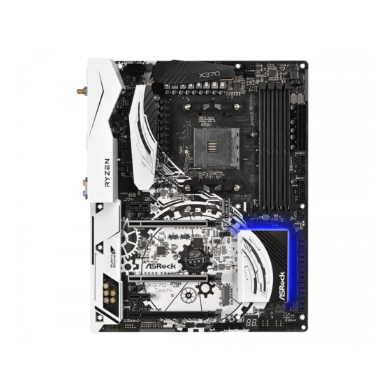
Page 3: Motherboard Layout
X370 Taichi Motherboard Layout CLRC BTN1 CPU_FAN1 ATX12V1 CPU_OPT/W_PUMP CHA_FAN3/W_PUMP M2_WIFI_1 USB 3.1 T: USB31_TA_1 B: USB31_TC_1 USB 3.0 Top: T: USB3 RJ-45 B: USB4 USB 3.0 T: USB5 B: USB6 AMD_FAN_LED1 USB_5 PCIE1 PCIE2 Ultra M.2 PCIe Gen3 x4... - Page 4 No. Description ATX 12V Power Connector (ATX12V1) CPU Fan / Waterpump Fan Connector (CPU_OPT/W_PUMP) CPU Fan Connector (CPU_FAN1) 2 x 288-pin DDR4 DIMM Slots (DDR4_A1, DDR4_B1) 2 x 288-pin DDR4 DIMM Slots (DDR4_A2, DDR4_B2) ATX Power Connector (ATXPWR1) USB 3.0 Header (USB3_9_10) USB 3.0 Header (USB3_7_8) AMD LED Fan USB Header (USB_5) AMD Fan LED Header (AMD_FAN_LED1)
- Page 5 X370 Taichi I/O Panel No. Description No. Description PS/2 Mouse/Keyboard Port (PS2_KB1) USB 3.0 Ports (USB3_5_6) LAN RJ-45 Port* USB 3.0 Ports (USB3_3_4) Central / Bass (Orange) USB 3.1 Type-A Port (USB31_TA_1) Rear Speaker (Black) USB 3.1 Type-C Port (USB31_TC_1)
- Page 6 ** If you use a 2-channel speaker, please connect the speaker’s plug into “Front Speaker Jack”. See the table below for connection details in accordance with the type of speaker you use. Audio Output Front Speaker Rear Speaker Central / Bass Line In Channels (No.
-
Page 7: Chapter 1 Introduction
If you require technical support related to this mother- board, please visit our website for specific information about the model you are using. You may find the latest VGA cards and CPU support list on ASRock’s website as well. ASRock website http://www.asrock.com. -
Page 8: Specifications
• 4 x DDR4 DIMM Slots • Supports DDR4 3200+(OC)/2933(OC)/2667/2400/2133 ECC & non-ECC, un-buffered memory* * Please refer to Memory Support List on ASRock’s website for more information. (http://www.asrock.com/) * Please refer to page 23 for DDR4 UDIMM maximum frequency support. - Page 9 X370 Taichi • Supports Purity Sound - Nichicon Fine Gold Series Audio Caps - 120dB SNR DAC with Differential Amplifier - TI® NE5532 Premium Headset Amplifier for Front Panel Audio Connector (Supports up to 600 Ohm headsets) - Pure Power-In...
- Page 10 M.2 PCI Express module up to Gen2 x4 (20 Gb/s)* * If M2_2 is occupied, PCIE5 slot will be disabled * Supports NVMe SSD as boot disks * Supports ASRock U.2 Kit Connector • 1 x Power LED and Speaker Header • 1 x AMD Fan LED Header...
- Page 11 Chassis, Chassis Optional/Water Pump Fans • Voltage monitoring: +12V, +5V, +3.3V, CPU Vcore, VCORE_ NB, DRAM, PCH 1.05V, +1.8V, VDDP • Microsoft® Windows® 10 64-bit * For the updated Windows® 10 driver, please visit ASRock’s website for details: http://www.asrock.com Certifica- • FCC, CE, WHQL tions • ErP/EuP ready (ErP/EuP ready power supply is required)
- Page 12 Please realize that there is a certain risk involved with overclocking, including adjusting the setting in the BIOS, applying Untied Overclocking Technology, or using third-party overclocking tools. Overclocking may affect your system’s stability, or even cause damage to the components and devices of your system. It should be done at your own risk and expense. We are not responsible for possible damage caused by overclocking.
-
Page 13: Chapter 2 Installation
X370 Taichi Chapter 2 Installation This is a ATX form factor motherboard. Before you install the motherboard, study the configuration of your chassis to ensure that the motherboard fits into it. Pre-installation Precautions Take note of the following precautions before you install motherboard components or change any motherboard settings. -
Page 14: Installing The Cpu
2.1 Installing the CPU Unplug all power cables before installing the CPU. - Page 15 X370 Taichi...
-
Page 16: Installing The Cpu Fan And Heatsink
2.2 Installing the CPU Fan and Heatsink After you install the CPU into this motherboard, it is necessary to install a larger heatsink and cooling fan to dissipate heat. You also need to spray thermal grease between the CPU and the heatsink to improve heat dissipation. Make sure that the CPU and the heatsink are securely fastened and in good contact with each other. - Page 17 X370 Taichi...
- Page 18 Installing the AM4 Box Cooler SR2...
- Page 19 X370 Taichi...
- Page 20 4-pin FAN cable RGB LED Cable +12V *The diagram shown here are for reference only. Please refer to page 31 for the orientation of AMD Fan LED Header (AMD_FAN_LED1).
- Page 21 X370 Taichi Installing the AM4 Box Cooler SR3...
- Page 23 X370 Taichi...
- Page 24 +12V Please note that only one cable should be used at a time in this step. If you select AMD_FAN_LED1, please install ASRock utility "ASRock RGB LED". If you select USB connector, please install AMD utility "SR3 Settings Software". *The diagram shown here are for reference only. Please refer to page 31 for the orientation of AMD Fan...
- Page 25 X370 Taichi 2.3 Installing Memory Modules (DIMM) This motherboard provides four 288-pin DDR4 (Double Data Rate 4) DIMM slots, and supports Dual Channel Memory Technology. 1. For dual channel configuration, you always need to install identical (the same brand, speed, size and chip-type) DDR4 DIMM pairs.
- Page 26 The DIMM only fits in one correct orientation. It will cause permanent damage to the motherboard and the DIMM if you force the DIMM into the slot at incorrect orientation.
- Page 27 X370 Taichi 2.4 Expansion Slots (PCI Express Slots) There are 5 PCI Express slots on the motherboard. Before installing an expansion card, please make sure that the power supply is switched off or the power cord is unplugged. Please read the documentation of the expansion card and make necessary hardware settings for the card before you start the installation.
-
Page 28: Jumpers Setup
2.5 Jumpers Setup The illustration shows how jumpers are setup. When the jumper cap is placed on the pins, the jumper is “Short”. If no jumper cap is placed on the pins, the jumper is “Open”. The illustration shows a 3-pin jumper whose pin1 and pin2 are “Short” when a jumper cap is placed on these 2 pins. -
Page 29: Onboard Headers And Connectors
X370 Taichi 2.6 Onboard Headers and Connectors Onboard headers and connectors are NOT jumpers. Do NOT place jumper caps over these headers and connectors. Placing jumper caps over the headers and connectors will cause permanent damage to the motherboard. System Panel Header... - Page 30 Power LED and Speaker Please connect the SPEAKER DUMMY Header chassis power LED and DUMMY (7-pin SPK_PLED1) the chassis speaker to this (see p.7, No. 21) header. PLED+ PLED+ PLED- Serial ATA3 Connectors These ten SATA3 (SATA3_1_2: connectors support SATA see p.7, No.
- Page 31 X370 Taichi USB 3.0 Header Besides four USB 3.0 ports Vbus Vbus Vbus IntA_PB_SSRX- (19-pin USB3_7_8) on the I/O panel, there IntA_PA_SSRX- IntA_PB_SSRX+ IntA_PA_SSRX+ (see p.7, No. 8) are two headers on this IntA_PB_SSTX- IntA_PA_SSTX- IntA_PB_SSTX+ (19-pin USB3_9_10) motherboard. Each USB...
- Page 32 Chassis Optional/Water This motherboard FAN_SPEED_CONTROL CHA_FAN_SPEED Pump Fan Connector provides two 4-Pin water FAN_VOLTAGE (4-pin CHA_FAN3/W_ cooling chassis fan PUMP) connectors. If you plan to (see p.7, No. 26) connect a 3-Pin chassis water cooler fan, please connect it to Pin 1-3. CPU Fan Connectors This motherboard pro- FAN_SPEED_CONTROL...
- Page 33 X370 Taichi RGB LED Headers These two RGB headers are used (4-pin RGB_LED1) to connect RGB LED extension 12V G R (see p.7, No. 24) cable which allows (4-pin RGB_LED2) users to choose from various LED (see p.7, No. 23) lighting effects.
-
Page 34: Smart Switch
2.7 Smart Switch The motherboard has Clear CMOS Switch, allowing users to quickly clear the CMOS values. Clear CMOS Switch Clear CMOS Switch (CLRCBTN) allows users to quickly (see p.9, No. 15) clear the CMOS values. This function is workable only when you power off your computer and unplug the power supply. - Page 35 X370 Taichi 2.8 M.2_SSD (NGFF) Module Installation Guide (M2_1) The M.2, also known as the Next Generation Form Factor (NGFF), is a small size and versatile card edge connector that aims to replace mPCIe and mSATA. The Ultra M.2 Socket (M2_1) supports SATA3 6.0 Gb/s module and M.2 PCI Express module up to Gen3 x4 (32 Gb/s).
- Page 36 Step 3 Move the standoff based on the module type and length. The standoff is placed at the nut location C by default. Skip Step 3 and 4 and go straight to Step 5 if you are going to use the default nut. Otherwise, release the standoff by hand.
- Page 37 X370 Taichi Step 6 Tighten the screw with a screwdriver to secure the module into place. Please do not overtighten the screw as this might damage the module. NUT2 NUT1...
- Page 38 SanDisk SATA Sandisk Z400s-SD8SNAT-128G-1122 SanDisk SATA SanDisk-SD6SN1M-128G Transcend SATA Transcend TS256GMTS800-256GB V-Color SATA V-Color 120G V-Color SATA V-Color 240G SATA WD GREEN WDS240G1G0B-00RC30 For the latest updates of M.2_SSD (NFGG) module support list, please visit our website for details: http://www.asrock.com...
- Page 39 X370 Taichi 2.9 M.2_SSD (NGFF) Module Installation Guide (M2_2) The M.2, also known as the Next Generation Form Factor (NGFF), is a small size and versatile card edge connector that aims to replace mPCIe and mSATA. The M.2 Sockets (M2_2) supports M.2 PCI Express module up to Gen2 x4 (20 Gb/s).
- Page 40 Step 3 Move the standoff based on the module type and length. The standoff is placed at the nut location D by default. Skip Step 3 and 4 and go straight to Step 5 if you are going to use the default nut. Otherwise, release the standoff by hand.
- Page 41 X370 Taichi M.2_SSD (NGFF) Module Support List Vendor Interface SanDisk PCIe SanDisk-SD6PP4M-128G( Gen2 x2) Intel PCIe INTEL 6000P-SSDPEKKF256G7 (nvme) Intel PCIe INTEL 6000P-SSDPEKKF512G7 (nvme) Intel PCIe INTEL 600P-SSDPEKKW128G7-128GB (nvme) Intel PCIe INTEL 600P-SSDPEKKW256G7-256GB (nvme) Kingston PCIe Kingston SHPM2280P2 / 240G (Gen2 x4)
- Page 42 1 Einleitung Vielen Dank, dass Sie sich für die X370 Taichi von ASRock entschieden haben – ein zuverlässiges Motherboard, das konsequent unter der strengen Qualitätskontrolle von ASRock hergestellt wurde. Es liefert ausgezeichnete Leistung mit robustem Design, das ASRock Streben nach Qualität und Beständigkeit erfüllt.
-
Page 43: Technische Daten
802.11ac-WLAN-Modul (an den rückseitigen I/O) • 15-μ-Goldkontakt in VGA-PCIe-Steckplatz (PCIE2) Audio • 7.1-Kanal-HD-Audio mit Inhaltsschutz (Realtek ALC1220- Audiocodec) • Erstklassige Blu-ray-Audiounterstützung • Unterstützt Überspannungsschutz (ASRock Full Spike Protection) • Unterstützt Purity Sound - Nichicon-Audiokappen der Fine Gold-Serie - 120-dB-SRV-DAC mit Differentialverstärker... - Page 44 - TI® NE5532 – erstklassiger Headset-Verstärker für Audioanschluss an der Frontblende (unterstützt Headsets mit bis zu 600 Ohm) - Reiner Stromeingang - Direct Drive Technology - PCB-isolierte Abschirmung - Impedanzerkennung am vorderen Ausgang - Individuelle PCB-Layer für rechten/linken Audiokanal - Goldene Audioanschlüsse - 15-μ-Gold-Audioanschluss • Unterstützt DTS Connect • Gigabit LAN 10/100/1000 Mb/s...
- Page 45 • 1 x M.2-Sockel (M2_2), unterstützt 2230-/2242-/2260-/2280-M.2-PCI-Express-Modul bis Gen2 x 4 (20 Gb/s)* * Wenn M2_2 belegt ist, wird PCIE5 deaktiviert * Unterstützt NVMe-SSD als Bootplatte * Unterstützt ASRock U.2-Kit Anschluss • 1 x Betrieb-LED- und Lautsprecher-Stiftleiste • 1 x AMD-Lüfter-LED-Stiftleiste • 2 x RGB-LED-Stiftleisten * Unterstützt bis zu 12 V/3 A, 36-W-LED-Streifen...
- Page 46 VCORE_NB, DRAM, PCH 1,05V, +1,8V, VDDP Betriebssys- • Microsoft® Windows® 10, 64 Bit * Einzelheiten zum aktualisierten Windows® 10-Treiber entneh- men Sie bitte der ASRock-Webseite:http://www.asrock.com Zertifizierun- • FCC, CE, WHQL • ErP/EuP ready (ErP/EuP ready-Netzteil erforderlich) * Detaillierte Produktinformationen finden Sie auf unserer Webseite: http://www.asrock.com...
- Page 47 X370 Taichi Bitte beachten Sie, dass mit einer Übertaktung, zu der die Anpassung von BIOS-Einstellungen, die Anwendung der Untied Overclocking Technology oder die Nutzung von Übertaktungswerkzeugen von Drittanbietern zählen, bestimmte Risiken verbunden sind. Eine Übertaktung kann sich auf die Stabilität Ihres Systems auswirken und sogar Komponenten und Geräte Ihres Systems beschädi- gen.
- Page 48 1.3 Jumpereinstellung Die Abbildung zeigt, wie die Jumper eingestellt werden. Wenn die Jumper-Kappe auf den Kontakten angebracht ist, ist der Jumper „kurzgeschlossen“. Wenn keine Jumper- Kappe auf den Kontakten angebracht ist, ist der Jumper „offen“. Die Abbildung zeigt einen 3-poligen Jumper, dessen Kontakt 1 und Kontakt 2 „kurzgeschlossen“ sind, wenn eine Jumper-Kappe auf diesen 2 Kontakten angebracht ist.
- Page 49 X370 Taichi 1.4 Integrierte Stiftleisten und Anschlüsse Integrierte Stiftleisten und Anschlüsse sind KEINE Jumper. Bringen Sie KEINE Jumper-Kappen an diesen Stiftleisten und Anschlüssen an. Durch Anbringen von Jumper-Kappen an diesen Stiftleisten und Anschlüssen können Sie das Motherboard dauerhaft beschädigen. Systemblende-Stiftleiste...
- Page 50 Betrieb-LED- und Bitte verbinden Sie SPEAKER DUMMY Lautsprecher-Stiftleiste die Betrieb-LED des DUMMY (7-polig, SPK_PLED1) Gehäuses und den (siehe S. 1, Nr. 21) Gehäuselautsprecher mit dieser Stiftleiste. PLED+ PLED+ PLED- Serial-ATA-III-Anschlüsse Diese zehn SATA-III- (SATA3_1_2: Anschlüsse unterstützen siehe S. 1, Nr. 12) SATA-Datenkabel für (SATA3_3_4: interne Speichergeräte mit...
- Page 51 X370 Taichi USB 3.0-Stiftleiste Neben vier USB 3.0-Ports Vbus Vbus Vbus IntA_PB_SSRX- (19-polig, USB3_7_8) an der E/A-Blende IntA_PA_SSRX- IntA_PB_SSRX+ IntA_PA_SSRX+ (siehe S. 1, Nr. 8) befinden sich zwei IntA_PB_SSTX- IntA_PA_SSTX- IntA_PB_SSTX+ (19-polig, USB3_9_10) Stiftleisten an diesem IntA_PA_SSTX+ IntA_PB_D- (siehe S. 1, Nr. 7) Motherboard.
- Page 52 Optionales-Gehäuse-/ Dieses Motherboard bietet zwei FAN_SPEED_CONTROL CHA_FAN_SPEED Wasserpumpen- 4-polige Wasserkühlung-Ge- FAN_VOLTAGE Lüfteranschluss häuselüfteranschlüsse. Falls (4-polig, CHA_FAN3/W_ Sie einen 3-poligen Gehäuse- PUMP) Wasserkühlerlüfter anschließen (siehe S. 1, Nr. 26) möchten, verbinden Sie ihn bitte mit Kontakt 1 bis 3. CPU-Lüfteranschlüsse Dieses Motherboard bietet FAN_SPEED_CONTROL CPU_FAN_SPEED (4-polig, CPU_FAN1)
- Page 53 X370 Taichi RGB-LED-Stiftleisten Diese beiden RGB-Stiftleisten (4-polig, RGB_LED1) dienen dem Anschließen eines 12V G R (siehe S. 1, Nr. 24) RGB-LED-Erweiterungskabels, (4-polig, RGB_LED2) das dem Nutzer die Auswahl zwis- (siehe S. 1, Nr. 23) chen verschiedenen LED-Lichtef- fekten ermöglicht. Achtung: Installieren Sie das RGB-LED-Kabel niemals falsch herum;...
- Page 54 1.5 Intelligente Schalter Das Motherboard hat ein intelligente Schalter: CMOS-löschen-Schalter, wodurch Benutzer das die CMOS-Werte löschen können. CMOS-löschen-Schalter Mit dem CMOS-löschen- (CLRCBTN) Schalter können Benutzer (siehe S. 3, Nr. 15) die CMOS-Werte schnell löschen. Diese Funktion ist nur verfügbar, wenn Sie Ihren Computer abschalten und die Stromver- sorgung unterbrechen.
- Page 55 Si vous avez besoin d’une assistance technique pour votre carte mère, veuillez visiter notre site Internet pour plus de détails sur le modèle que vous utilisez. La liste la plus récente des cartes VGA et des processeurs pris en charge est également disponible sur le site Internet de ASRock. Site Internet ASRock http://www.asrock.com.
- Page 56 Processeur • Prend en charge les CPU Ryzen (Summit Ridge) à socket AMD • PWM numérique IR • Alimentation à 16 phases • Prend en charge le moteur Hyper BCLK II ASRock Chipset • AMD Promontory X370 Mémoire • Technologie mémoire double canal DDR4 • 4 x fentes DIMM DDR4...
- Page 57 X370 Taichi - Technologie Direct Drive - Blindage isolant PCB - Détection de l'impédance sur le port de sortie avant - Couches de PCB individuelles pour canal audio D/G - Connecteurs jack audio - Connecteur audio or 15μ • Prend en charge DTS Connect Réseau...
- Page 58 Gb/s)* * Si M2_2 est occupé, PCIE5 est désactivé * Prend en charge les SSD NVMe comme disques de démarrage * Prend en charge le kit ASRock U.2 Connecteur • 1 x prise LED d’alimentation et haut-parleur • 1 x embase LED de Ventilateur AMD • 2 x embase LED RVB...
- Page 59 * Pour le pilote mis à jour pour Windows® 10, veuillez visiter le site Web d'ASRock pour plus de détails : http://www.asrock.com * pour des informations détaillées de nos produits, veuillez visiter notre site : http://www.asrock.com Il est important de signaler que l’ o vercloking présente certains risques, incluant des modifi- cations du BIOS, l’...
- Page 60 1.3 Configuration des cavaliers (jumpers) L’illustration ci-dessous vous renseigne sur la configuration des cavaliers (jumpers). Lorsque le capuchon du cavalier est installé sur les broches, le cavalier est « court- circuité ». Si le capuchon du cavalier n’ e st pas installé sur les broches, le cavalier est « ouvert ».
- Page 61 X370 Taichi 1.4 Embases et connecteurs de la carte mère Les embases et connecteurs situés sur la carte NE SONT PAS des cavaliers. Ne placez JAMAIS de capuchons de cavaliers sur ces embases ou connecteurs. Placer un capuchon de cavalier sur ces embases ou connecteurs endommagera irrémédiablement votre carte mère.
- Page 62 Prise LED d’alimentation Veuillez brancher la LED SPEAKER DUMMY et haut-parleur d'alimentation du châssis DUMMY (SPK_PLED1 à 7 broches) et le haut-parleur du (voir p.1, No. 21) châssis sur ce connecteur. PLED+ PLED+ PLED- Connecteurs Serial ATA3 Ces dix connecteurs (SATA3_1_2: SATA3 sont compatibles voir p.1, No.
- Page 63 X370 Taichi Embases USB 3.0 En plus des quatre ports USB Vbus Vbus Vbus IntA_PB_SSRX- (USB3_7_8 à 19 broches) 3.0 sur le panneau E/S, cette IntA_PA_SSRX- IntA_PB_SSRX+ IntA_PA_SSRX+ (voir p.1, No. 8) carte mère est dotée de deux IntA_PB_SSTX- IntA_PA_SSTX- IntA_PB_SSTX+ (USB3_9_10 à...
- Page 64 Connecteur du ventilateur Cette carte mère est dotée de FAN_SPEED_CONTROL de châssis optionnel/ deux connecteurs pour venti- CHA_FAN_SPEED FAN_VOLTAGE pompe à eau lateur de châssis à refroidisse- (CHA_FAN3/W_PUMP à ment par eau à 4 broches. Si 4 broches) vous envisagez de connecter un (voir p.1, No.
- Page 65 X370 Taichi Embase LED RVB Ces deux embases RVB servent (RGB_LED1 à 4 broches) à connecter le câble d'extension 12V G R (voir p.1, No. 24) LED RVB qui permet aux utilisa- (RGB_LED2 à 4 broches) teurs de choisir parmi plusieurs (voir p.1, No.
- Page 66 1.5 Boutons intelligents La carte mère est équipée de un boutons intelligents : bouton d’ e ffacement CMOS qui permettent aux utilisateurs d’ e ffacer les valeurs CMOS en toute simplicité. Bouton d’ e ffacement CMOS Le bouton d’ e ffacement (CLRCBTN) CMOS permet aux (voir p.3, No.
- Page 67 Web di ASRock senza ulteriore preavviso. Per il supporto tecnico correlato a questa scheda madre, visitare il nostro sito Web per informazioni specifiche relative al modello attualmente in uso.
- Page 68 • Fattore di forma ATX • Supporta CPU Ryzen (Summit Ridge) AMD AM4 Socket • PWM Digitale IR • Potenza a 16 fasi • Supporto di ASRock Hyper BCLK Engine II Chipset • AMD Promontory X370 Memoria • Tecnologia memoria DDR4 Dual Channel • 4 x alloggi DIMM DDR4...
- Page 69 X370 Taichi - Tecnologia Direct Drive - Schermatura isolata PCB - Rilevamento di impedenza su porta uscita anterioe - Layer PCB individuali per canali audio R/L - Connettori audio dorati - Connettore audio dorato 15μ • Supporta DTS Connect • Gigabit LAN 10/100/1000 Mb/s • GigaLAN Intel®...
- Page 70 M.2 PCI Express fino a Gen2 x4 (20 Gb/s)* * Se l’alloggio M2_2 è occupato, l’alloggio PCIE5 viene disabilitato * Supporto di SSD NVMe come disco d’avvio * Supporta kit ASRock U.2 Connettore • 1 x connettore LED alimentazione e altoparlante • 1 x collettore LED AMD Fan...
- Page 71 • Monitoraggio tensione: +12V, +5V, +3,3V, CPU Vcore, VCORE_ NB, DRAM, PCH 1,05V, +1,8V, VDDP • Microsoft® Windows® 10 64 bit * Per il driver aggiornato di Windows® 10, visitare il sito ASRock all’indirizzo: http://www.asrock.com Certificazioni • FCC, CE, WHQL • ErP/EuP Ready (è...
- Page 72 1.3 Impostazione jumper L'illustrazione mostra in che modo vengono impostati i jumper. Quando il cappuccio del jumper è posizionato sui pin, il jumper è "cortocircuitato". Se sui pin non è posizionato alcun cappuccio del jumper, il jumper è "aperto". L'illustrazione mostra un jumper a 3 pin i cui pin1 e pin2 sono "cortocircuitati"...
- Page 73 X370 Taichi 1.4 Header e connettori sulla scheda Gli header e i connettori sulla scheda NON sono jumper. NON posizionare cappucci del jumper su questi header e connettori. Il posizionamento di cappucci del jumper su header e connettori provocherà danni permanenti alla scheda madre.
- Page 74 Connettore LED Collegare i LED alimentazione SPEAKER DUMMY alimentazione e e l’altoparlante a questo connet- DUMMY altoparlante tore. (SPK_PLED1 7 pin) (vedere pag. 1, n. 23) PLED+ PLED+ PLED- Connettori Serial ATA3 Questi dieci connettori SATA3 (SATA3_1_2: supportano cavi di trasmissione vedere pag.
- Page 75 X370 Taichi Header USB 3.0 Oltre alle quattro porte USB Vbus Vbus Vbus IntA_PB_SSRX- (USB3_7_8 a 19 pin) 3.0 sul pannello I/O, su questa IntA_PA_SSRX- IntA_PB_SSRX+ IntA_PA_SSRX+ (vedere pag. 1, n. 8) scheda madre vi sono due IntA_PB_SSTX- IntA_PA_SSTX- IntA_PB_SSTX+ (USB3_9_10 a 19 pin) header.
- Page 76 Connettore ventola Questa scheda madre fornisce FAN_SPEED_CONTROL CHA_FAN_SPEED telaio optional / pompa due connettori ventola telaio FAN_VOLTAGE dell'acqua con raffreddamento ad acqua (4 pin CHA_FAN3/W_ a 4 pin. Se si decide di colle- PUMP) gare una ventola telaio con (vedere pag. 1, n. 26) raffreddamento ad acqua a 3 pin, collegarla al pin 1-3.
- Page 77 X370 Taichi Collettore LED RGB Questi due collettori RGB ven- (RGB_LED1 a 4 pin) gono utilizzati per collegare la 12V G R (vedere pag. 1, n. 24) prolunga LED RGB, che consente (RGB_LED2 a 4 pin) agli utenti di scegliere tra vari (vedere pag.
- Page 78 1.5 Interruttori intuitivi La scheda madre è dotata di uno interruttori intuitivi: interruttore Clear CMOS, che consentono di cancellare i valori CMOS. Interruttore Clear CMOS L’interruttore Clear CMOS (CLRCBTN) consente di cancellare (fare riferimento a pagina 3, rapidamente i valori CMOS. Numero 15) Questa funzione è...
-
Page 79: Contenido Del Paquete
Si esta documentación sufre alguna modificación, la versión actualizada estará disponible en el sitio web de ASRock sin previo aviso. Si necesita asistencia técnica relacionada con esta placa base, visite nuestro sitio web para obtener información específica sobre el modelo que esté... - Page 80 • Admite memoria DDR4 3200+(OC)/2933(OC)/2667/2400/2133 ECC & no ECC, sin búfer* * Para obtener más información, consulte la lista de memorias compatibles en el sitio web de ASRock. (http://www.asrock.com/) * Consulte la página 23 para conocer las frecuencias máximas com- patibles de DDR4 UDIMM.
- Page 81 X370 Taichi - Tecnología Direct Drive - Protección de aislamiento PCB (circuito impreso) - Detección de impedancia en el puerto de salida delantero - Capas PCB individuales para canal de audio D/I - Conectores de audio de oro - Conector de audio dorado de 15μ...
- Page 82 * Si M2_2 está ocupado, PCIE5 se deshabilitará * Admite unidad de estado sólido de NVMe como disco de arranque * Admiteel Kit U.2 de ASRock Conector • 1 x LED de alimentación y base de conexiones para el altavoz • 1 x Base de conexiones de LED de Ventilador AMD...
- Page 83 Web desde ASRock para obtener detalles: http://www.asrock.com Certificaciones • FCC, CE y WHQL • Preparado para ErP/EuP (se necesita una fuente de alimentac- ión preparada para ErP/EuP) * Para obtener información detallada del producto, visite nuestro sitio Web: http://www.asrock.com...
- Page 84 Tenga en cuenta que hay un cierto riesgo implícito en las operaciones de aumento de la velocidad del reloj, incluido el ajuste del BIOS, aplicando la tecnología de aumento de velocidad liberada o utilizando las herramientas de aumento de velocidad de otros fabricantes. El aumen- to de la velocidad puede afectar a la estabilidad del sistema e, incluso, dañar los componentes y dispositivos del sistema.
- Page 85 X370 Taichi 1.3 Instalación de los puentes La instalación muestra cómo deben instalarse los puentes. Cuando la tapa de puente se coloca en los pines, el puente queda “Corto”. Si no coloca la tapa de puente en los pines, el puente queda “Abierto”. La ilustración muestra un puente de 3 pines cuyo pin 1 y pin 2 son “Cortos”...
- Page 86 1.4 Conectores y cabezales incorporados Los cabezales y conectores incorporados NO son puentes. NO coloque tapas de puente sobre estos cabezales y conectores. Si coloca tapas de puente sobre los cabezales y conectores dañará de forma permanente la placa base. Cabezal del panel del sistema Conecte el interruptor de PLED+...
- Page 87 X370 Taichi LED de alimentación y base de Conecte el LED de ali- SPEAKER DUMMY conexiones para la altavoz mentación del chasis y el DUMMY (SPK_PLED1 de 7 contactos) altavoz del chasis a esta (consulte la pág.1, Nº 21) base de conexiones.
- Page 88 Cabezal USB 3.0 Además de cuatro puertos Vbus Vbus Vbus IntA_PB_SSRX- (USB3_7_8 de 19 contactos) USB 3.0 en el panel I/O, IntA_PA_SSRX- IntA_PB_SSRX+ IntA_PA_SSRX+ (consulte la pág.1, Nº 8) esta placa base contiene IntA_PB_SSTX- IntA_PA_SSTX- IntA_PB_SSTX+ (USB3_9_10 de 19 pines) dos cabezales.
- Page 89 X370 Taichi Conector del ventilador de Esta placa base proporciona FAN_SPEED_CONTROL CHA_FAN_SPEED la bomba de agua/opcional dos conectores de ventilador FAN_VOLTAGE del chasis del chasis de refrigeración (CHA_FAN3/W_PUMPde por agua de 4 contactos. Si 4 contactos) tiene pensando conectar un (consulte la pág.1, N.º...
- Page 90 Cabezales de LED RGB Estas dos bases de conexiones (RGB_LED1 de 4 pines) RGB se utilizan para conectar 12V G R (consulte la pág.1, Nº 24) el alargador de LED RGB que (RGB_LED2 de 4 pines) permite a los usuarios elegir entre (consulte la pág.1, N.º23) varios efectos de iluminación de LED.
- Page 91 X370 Taichi 1.5 Interruptores inteligentes La placa base contiene uno interruptores inteligentes: interruptor de borrado de CMOS; que permiten a los usuarios borrar los valores de CMOS. Interruptor de borrado de El interruptor de borrado de CMOS CMOS permite a los usuarios (CLRCBTN) borrar rápidamente los valores...
- Page 92 1 Введение Благодарим вас за приобретение надежной системной платы ASRock X370 Taichi, выпускаемой под постоянным жестким контролем качества компании ASRock. Эта материнская плата обеспечивает великолепную производительность и отличается надежной конструкцией в соответствии с требованиями компании ASRock в отношении качества и долговечности.
- Page 93 ЦП • Поддерживаются процессоры AMD AM4 CPU Ryzen (Summit Ridge) под сокет • Цифровой ШИМ-контроллер IR • Система питания 16 • Поддержка системы ASRock Hyper BCLK Engine II Чипсет • AMD Promontory X370 Память • Двухканальная память DDR4 • 4 x гнезда DDR4 DIMM • Поддерживаются...
- Page 94 – Первоклассный усилитель TI® NE5532 для гарнитуры у аудиоразъема на передней панели (поддерживаются гарнитуры с сопротивлением до 600 Ом) - Стабилизированный вход питания - Технология Direct Drive - Изолирующее экранирование печатной платы - Определение сопротивления нагрузки на аудиовыходе на передней панели - Отдельные...
- Page 95 типа 2230/2242/2260/2280 до версии Gen2 x4 (20 ГБ/с)* * Если занят слот M2_2, отключается слот PCIE5. * Поддерживаются в качестве загрузочных SSD-диски типа NVMe. * Поддержка комплекта ASRock U.2 Разъемы • 1 x колодка светодиодного индикатора питания и динамика корпуса...
- Page 96 ядра ЦП, VCORE_NB, DRAM, PCH 1,05B, +1,8V, VDDP Операционные • Microsoft® Windows® 10 (64-разрядная) системы * Подробные сведения об обновлении драйвера для Win- dows® 10 представлены на веб-сайте ASRock: http://www. asrock.com Сертификация • FCC, CE, WHQL • Совместимость с ErP/EuP (необходим блок питания,...
- Page 97 X370 Taichi * С дополнительной информацией об изделии можно ознакомиться на веб-сайте: http://www.asrock.com Следует учитывать, что разгон процессора, включая изменение настроек BIOS, применение технологии Untied Overclocking и использование инструментов разгона независимых производителей, сопряжен с определенным риском. Разгон процессора может снизить стабильность системы или даже привести к повреждению ее...
- Page 98 1.3 Установка перемычек Установка перемычек показана на рисунке. При установке колпачковой перемычки на контакты перемычка «замкнута». Если колпачковая перемычка на контакты не установлена, перемычка «разомкнута». На рисунке показана 3-контактная перемычка с замкнутыми контактами 1 и 2 при установке на них колпачковой...
- Page 99 X370 Taichi 1.4 Колодки и разъемы, расположенные на материнской плате Расположенные на материнской плате колодки и разъемы перемычками НЕ являются. НЕ устанавливайте на эти колодки и разъемы колпачковые перемычки. Установка колпачковых перемычек на эти колодки и разъемы может вызвать неустранимое...
- Page 100 Колодка светодиодного Предназначена SPEAKER индикатора питания и DUMMY для подключения DUMMY динамика корпуса светодиодного (7-контактная, индикатора питания и SPK_PLED1) динамика корпуса. PLED+ (см. стр. 1, № 21) PLED+ PLED- Разъемы Serial ATA3 Эти десять SATA3 (SATA3_1_2: предназначены для см. стр. 1, № 12) подключения...
- Page 101 X370 Taichi Колодка USB 3.0 Кроме четырех портов Vbus Vbus Vbus IntA_PB_SSRX- (19-контактная, USB 3.0 на панели ввода- IntA_PA_SSRX- IntA_PB_SSRX+ IntA_PA_SSRX+ USB3_7_8) вывода на материнской IntA_PB_SSTX- IntA_PA_SSTX- IntA_PB_SSTX+ (см. стр. 1, № 8) плате также есть две IntA_PA_SSTX+ IntA_PB_D- (19-контактная, колодки.
- Page 102 Разъем для Данная материнская плата FAN_SPEED_CONTROL CHA_FAN_SPEED дополнительного оснащена двумя 4-контактными FAN_VOLTAGE вентилятора или помпы разъемами для системы водяного охлаждения водяного охлаждения корпуса. корпуса 3-контактную систему водяного (4-контактный CHA_FAN3/ охлаждения корпуса следует W_PUMP) подключать к контактам 1–3. (см. стр. 1,№ 26) Разъемы...
- Page 103 X370 Taichi Колодки для подключения Эти две колодки для RGB- светодиодной RGB- подсветки служат для подключения 12V G R подсветки. удлинительного кабеля (4-контактная, RGB_LED1) светодиодной RGB-подсветки, (см. стр. 1, № 24) которая позволяет реализовать (4-контактная, RGB_LED2) различные световые эффекты. (см. стр. 1, № 23) Внимание! Категорически...
- Page 104 1.5 Электронные кнопки Материнская плата снабжена одна электронными кнопками: переключатель сброса настроек CMOS, предназначенными для обнуления значений CMOS. Кнопка сброса настроек CMOS Кнопка сброса настроек (CLRCBTN) CMOS предназначена (См. стр. 3, № 15) для быстрого обнуления значений CMOS. Эта функция работает только, если питания компьютера выключено и он отключен от...
- Page 105 Se precisar de assistência técnica relacionada a esta placa principal, visite o nosso site para obter informações específicas sobre o modelo que estiver utilizando. Você também poderá encontrar a lista de placas VGA e CPU mais recentes suportadas no site da ASRock. Site da ASRock http://www.asrock.com.
- Page 106 • Formato ATX • Suporta Soquete AMD AM4 CPUs Ryzen (Summit Ridge) • Energia Digital IR • Design com 16 fases de alimentação • Suporta Mecanismo ASRock Hyper BCLK II Chipset • AMD Promontory X370 Memória • Tecnologia de memória DDR4 de dois canais • 4 x Slots DIMM DDR4...
- Page 107 X370 Taichi - Tecnologia de drive direto - Blindagem de isolamento PCB - Sensor de Impedância na Saída da Porta Dianteira - Camadas de PCB individuais por canal de áudio R/L - Fonres de Áudio Gold - Conector de Áudio de Outro 15μ...
- Page 108 2230/2242/2260/2280 M.2 PCI Express até Gen2 x4 (20 Gb/s)* * Se M2_2 estiver ocupado, PCIE5 será desativado * Suporta NVMe SSD nos discos de inicialização * Suporta Kit U.2 ASRock Conector • 1 x LED de alimentação e Cabeçote de Autofalante • 1 x Cabeçote AMD Fan LED...
- Page 109 ASRock para mais detalhes: http://www.asrock.com Certificações • FCC, CE, WHQL • Preparada para ErP/EuP (é necessária uma fonte de alimen- tação preparada para ErP/EuP) * Para obter informações detalhadas sobre o produto, por favor, visite o nosso site: http://www.asrock.com...
- Page 110 Por favor, observe que existe um certo risco envolvendo overclocking, incluindo o ajuste das definições na BIOS, a aplicação de tecnologia Untied Overclocking ou a utilização de ferra- mentas de overclocking de terceiros. O overclocking poderá afetar a estabilidade do sistema ou mesmo causar danos nos componentes e dispositivos do seu sistema.
- Page 111 X370 Taichi 1.3 Configuração dos jumpers A imagem abaixo mostra como os jumpers são configurados. Quando a tampa do jumper é colocada nos pinos, o jumper é "Curto". Se não for colocada uma tampa de jumper nos pinos, o jumper é "Aberto". A imagem mostra um jumper de 3 pinos cujos pino1 e pino2 estão "Curtos"...
- Page 112 1.4 Suportes e conectores onboard Os conectores e suportes onboard NÃO são jumpers. NÃO coloque tampas de jumpers sobre es- tes terminais e conectores Colocar tampas de jumpers sobre os terminais e conectores irá causar danos permanentes à placa-mãe. Suporte do painel de sistema Ligue o botão de alimentação, PLED+ PLED-...
- Page 113 X370 Taichi LED de alimentação e Conecte o LED de ali- SPEAKER DUMMY Cabeçote de Autofalante mentação do chassi e o DUMMY (SPK_PLED1 7 pinos) autofalante do chassi a este (ver p.1, N.º 21) cabeçote. PLED+ PLED+ PLED- Conectores série ATA3...
- Page 114 Suporte USB 3.0 Além das quatro portas Vbus Vbus Vbus IntA_PB_SSRX- (USB3_7_8 de 19 pinos) USB 3.0 no painel de E/ IntA_PA_SSRX- IntA_PB_SSRX+ IntA_PA_SSRX+ (ver p.1, N.º 8) S, existem dois suportes IntA_PB_SSTX- IntA_PA_SSTX- IntA_PB_SSTX+ (USB3_9_10 de 19 pinos) nesta placa principal. Cada IntA_PA_SSTX+ IntA_PB_D- (ver p.1, N.º...
- Page 115 X370 Taichi Chassis Opcional / Esta placa mãe fornece conec- FAN_SPEED_CONTROL CHA_FAN_SPEED Conector da ventoinha de tores de ventilador do chassis de FAN_VOLTAGE bomba de água refrigeração a água de 4 pinos. (4-pinos CHA_FAN3/W_ Se você pretende conectar um PUMP) ventilador de refrigeração a água...
- Page 116 Cabeçotes de LED RGB Estes dois cabeçotes RGB são (RGB_LED1 de 4 pinos) usados para conectar o cabo de 12V G R (ver p.1, N.º 24) extensão de LED RGB que permite (RGB_LED2 de 4 pinos) aos usuários escolher entre vários (ver p.1, N.º...
- Page 117 X370 Taichi 1.5 Interruptores inteligentes A placa-mãe tem um chaves inteligentes: limpar os valores CMOS. Interruptor para apagar o CMOS O interruptor para apagar o (CLRCBTN) CMOS permite aos usuários (ver p.3, N.º 17) apagar os valores CMOS rapidamente. Esta função pode ser utilizada apenas quando o computador e a fonte de alimentação estiverem...
- Page 118 Bu belgeler üzerinde herhangi bir değişiklik yapılması durumunda, güncellenmiş sürüm, herhangi bir bildirim yapılmaksızın ASRock'ın web sitesinde yer alacaktır. Bu ana kartla ilgili olarak teknik destek almak isterseniz, lütfen kullandığınız model hakkında özel bilgiler için web sitemizi ziyaret edin. En güncel VGA kartları...
- Page 119 • 4 x DDR4 DIMM Yuvası • DDR4 3200+(OC)/2933(OC)/2667/2400/2133 ECC & ECC olmayan, arabelleksiz bellek* * Ayrıntılı bilgi için ASRock'ın web sitesindeki Bellek Desteği Listesine bakın. (http://www.asrock.com/) * Lütfen DDR4 UDIMM maksimum frekans desteği için bkz. sayfa • En fazla sistem belleği kapasitesi: 64GB • DIMM Yuvalarında 15 μ...
- Page 120 - Doğrudan Bağlantı Teknolojisi - PCB Ayrı Koruma - Ön Çıkış bağlantı noktasında Empedans Algılama - Sağ/Sol Ses Kanalı için Bireysel PCB Katmanları - Altın Ses Girişleri - 15 μ Altın Ses Bağlayıcı • DTS Connect işlevini destekler • Gigabit LAN 10/100/1000 Mb/s • GigaLAN Intel®...
- Page 121 2230/2242/2260/2280 M.2 PCI Express modülü destekler* * M2_2 meşgulse PCIE5 devre dışı bırakılacaktır. * Önyükleme diskleri olarak NVMe SSD destekler * ASRock U.2 Takımını destekler Bağlayıcı • 1 x Güç LED’i ve Hoparlör Bağlantısı • 1 x AMD Fan LED Bağlantısı...
- Page 122 Pompalı, Kasa, Kasa İsteğe Bağlı/Su Pompalı Fanlar • Gerilim izleme: +12V, +5V, +3,3V, İşlemci Vcore, VCORE_NB, DRAM, PCH 1,05V, +1,8V, VDDP İşletim Sistemi • Microsoft® Windows® 10 64-bit * Güncellenmiş Windows® 10 sürücüsü konusunda ayrıntılar için lütfen ASRock web sitesini ziyaret edin: http://www.asrock.com...
- Page 123 X370 Taichi * Detaylı ürün bilgisi için lütfen web sitemizi ziyaret edin: http://www.asrock.com Lütfen, BIOS ayarlarını düzenleme, Bağımsız Hız Aşırtma Teknolojisinin uygulanması veya üçüncü taraf hız aşırtma araçlarının kullanılması da dâhil olmak üzere tüm hız aşırtma işlem- lerinin belirli bir risk taşıdığını unutmayın. Hız aşırtma, sisteminizin dayanıklılığını etkileyebil- ir, hatta sisteminizde yer alan bileşenlere ve aygıtlara zarar verebilir.
- Page 124 1.3 Bağlantı Teli Kurulumu Çizim, bağlantı tellerinin kurulumunu göstermektedir. Tel kapağı, pimlerin üzerine yerleştirildiğinde, tel "Kısa" olur. Pimlerin üzerinde tel kapağı bulunmadığında, tel "Açık" olur. Çizim, pin1 ve pin2 alanları "Kısa" olan ve bu iki pim üzerinde bir bağlantı teli kapağı bulunan 3 pimli bağlantı telini göstermektedir. CMOS'u Temizle Bağlantı...
- Page 125 X370 Taichi 1.4 Yerleşik Bağlantılar ve Bağlayıcılar Yerleşik bağlantılar ve bağlayıcılar bağlantı teli değildir. Bağlantı teli kapaklarını bu bağlantı ve bağlayıcılar üzerine yerleştirmeyin. Bağlantı teli kapaklarının bağlantılar ve bağlayıcılar üzerine yerleştirilmesi ana karta kalıcı hasar verebilir. Sistem Paneli Bağlantısı Güç anahtarını bağlayın,...
- Page 126 Güç LED’i ve Hoparlör Lütfen kasa güç LED’ini SPEAKER DUMMY Bağlantısı ve kasa hoparlörünü bu DUMMY (7 pimli SPK_PLED1) bağlantıya takın. (bkz. s.1, No. 21) PLED+ PLED+ PLED- Seri ATA3 Bağlayıcıları Bu on SATA3 bağlayıcısı, (SATA3_1_2: veri aktarım hızı 6,0 Gb/ bkz.
- Page 127 X370 Taichi USB 3.0 Bağlantı Bu anakart üzerinde, I/O Vbus Vbus Vbus IntA_PB_SSRX- (19-pin USB3_7_8) paneli üzerindeki dört USB 3.0 IntA_PA_SSRX- IntA_PB_SSRX+ IntA_PA_SSRX+ (bkz. s.1, No. 8) bağlantı noktasının yanı sıra, IntA_PB_SSTX- IntA_PA_SSTX- IntA_PB_SSTX+ (19 pimli USB3_9_10) iki adet bağlantı bulunmaktadır.
- Page 128 Kasa İsteğe Bağlı/Su Bu anakart, iki 4-Pinli FAN_SPEED_CONTROL CHA_FAN_SPEED Pompası Fan Bağlayıcısı su soğutmalı kasa fan FAN_VOLTAGE (4 pimli CHA_FAN3/W_ bağlayıcısına sahiptir. Bir PUMP) 3-Pin kasa su soğutmalı fan (bkz. s.1, No. 26) bağlamayı planlıyorsanız, lütfen Pin 1-3'e bağlayın. İşlemci Fan Bağlayıcıları Bu ana kart, 4 pimli bir FAN_SPEED_CONTROL CPU_FAN_SPEED...
- Page 129 X370 Taichi RGB LED Bağlantısı Bu iki RGB bağlantısı, kul- (4 pimli RGB_LED1) lanıcıların çeşitli LED aydın- 12V G R (bkz. s.1, No. 24) latma efektleri arasında seçim (4 pimli RGB_LED2) yapmasına izin veren RGB LED (bkz. p.1, No. 23) uzatma kablosunu bağlamak için...
- Page 130 1.5 Akıllı Anahtarlar Ana kartta bir adet akıllı anahtar bulunur: CMOS değerlerini temizlemelerini sağlar. CMOS Temizleme Düğmesi CMOS Temizleme Düğmesi (CLRCBTN) kullanıcıların CMOS (bkz. sf. 3, No. 15) değerlerini hızlı bir şekilde temizlemelerini sağlar. Bu işlev yalnızca bilgisayarınızı kapattığınızda ve fişini prizden çektiğinizde çalışır.
- Page 131 제공합니다 . 마더보드 규격과 BIOS 소프트웨어를 업데이트할 수도 있기 때문에 , 이 문서의 내용은 예고 없이 변경될 수 있습니다 . 이 설명서가 변경될 경우 , 업데이트된 버전은 ASRock 의 웹사이트에서 추가 통지 없이 제공됩니다 . 이 마더보드와 관련하여 기술적 지원이...
- Page 132 • DDR4 DIMM 슬롯 4 개 • DDR4 3200+(OC)/2933(OC)/2667/2400/2133 ECC & 비 ECC, 비버퍼링 메모리 지원 * * 추가 정보를 원하시면 ASRock 웹사이트에 있는 메모리 지원 목록을 참조하십시오 . (http://www.asrock.com/) * DDR4 UDIMM 최대 주파수 지원은 23 페이지를 참조하십시 오 .
- Page 133 X370 Taichi - 디퍼렌셜 증폭기 포함 120dB SNR DAC - 전면 패널 오디오 커넥터용 TI® NE5532 프리미엄 헤드셋 증폭기 ( 최대 600 옴 헤드셋 지원 ) - 순수 전원 입력 - 다이렉트 드라이브 기술 - PCB 절연 차폐 - 전면 출력 포트의 임피던스 감지...
- Page 134 Gen2 M.2 PCI Express 모듈 4 개 지원 (20 Gb/s)* * M2_2 가 사용 중일 경우 , PCIE5 가 비활성화됩니다 * NVMe SSD 를 부팅 디스크로 사용 가능하도록 지원 * ASRock U.2 키트 지원 • 전원 LED 및 스피커 헤더 1 개 커넥터...
- Page 135 인증 • ErP/EuP 사용 가능 (ErP/EuP 사용 가능 전원공급장치 필요 ) * 자세한 제품 정보에 대해서는 당사 웹사이트를 참조하십시오 : http://www.asrock.com BIOS 설정을 조정하거나 Untied Overclocking Technology 를 적용하거나 타업체의 오 버클로킹 도구를 사용하는 것을 포함하는 오버클로킹에는 어느 정도의 위험이 따른...
- Page 136 1.3 점퍼 설정 그림은 점퍼를 어떻게 설정하는지 보여줍니다 . 점퍼 캡을 핀에 씌우면 점퍼가 “단락” 됩니다 . 점퍼 캡을 핀에 씌우지 않으면 점퍼가 “단선”됩니다 . 그림 은 3 핀 점퍼를 보여주며 핀 1 과 핀 2 는 점퍼 캡을 씌울 때 “단락”됩니다 . Clear CMOS 점퍼...
- Page 137 X370 Taichi 1.4 온보드 헤더 및 커넥터 온보드 헤더와 커넥터는 점퍼가 아닙니다 . 점퍼 캡을 온보드 헤더와 커넥터에 씌우지 마십시오 . 점퍼 캡을 온보드 헤더와 커넥터에 씌우면 마더보드가 영구적으로 손상됩 니다 . 섀시의 전원 스위치 , 리 시스템 패널 헤더...
- Page 138 전원 LED 및 스피커 헤더 섀시 전원 LED 와 섀시 SPEAKER DUMMY (7 핀 SPK_PLED1) 스피커를 이 헤더에 연결 DUMMY (1 페이지 , 21 번 항목 참조 ) 하십시오 . PLED+ PLED+ PLED- 시리얼 ATA3 커넥터 이들 10 개의 SATA3 커넥 (SATA3_1_2: 터는...
- Page 139 X370 Taichi USB 3.0 헤더 I/O 패널에 USB 3.0 포트 Vbus Vbus Vbus IntA_PB_SSRX- (19 핀 USB3_7_8) 네 개가 탑재되어 있을 IntA_PA_SSRX- IntA_PB_SSRX+ IntA_PA_SSRX+ (1 페이지 , 8 번 항목 참조 ) 뿐 아니라 마더보드에 헤 IntA_PB_SSTX- IntA_PA_SSTX- IntA_PB_SSTX+ (19 핀 USB3_9_10) 더...
- Page 140 CPU/ 섀시 옵션 / 워터 펌프 이 마더보드에는 4 핀 FAN_SPEED_CONTROL CHA_FAN_SPEED 팬 커넥터 수냉식 섀시 팬 커넥터 FAN_VOLTAGE (4 핀 CHA_FAN3/W_ 2 개가 탑재되어 있습 PUMP) 니다 . 3 핀 CPU 섀시 (1 페이지 , 26 번 항목 참조 ) 수냉식...
- Page 141 X370 Taichi RGB LED 헤더 이 2 개의 RGB 헤더는 다양한 (4 핀 RGB_LED1) LED 조명 효과를 선택할 수 12V G R (1 페이지 , 24 번 항목 참조 ) 있는 RGB LED 연장 케이블을 (4 핀 RGB_LED2) 연결하는 데 사용됩니다 .
- Page 142 1.5 스마트 스위치 마더보드에는 스마트 스위치 한 개가 탑재되어 있습니다 : CMOS 지우기 스위 치 . 리 CMOS 값을 지우게 할 수 있습니다 . CMOS 지우기 스위치 CMOS 지우기 스위치로 (CLRCBTN) CMOS 값을 빨리 지울 수 (3 페이지 , 15 번 항목 참조 ) 있습니다...
- Page 143 マザーボードの仕様と BIOS ソフトウェアは更新されるこ とがあるため、 このマニュアル の内容は予告なしに変更するこ とがあります。 このマニュアルの内容に変更があった場 合には、 更新されたバージョンは、 予告なくASRock のウェブサイ トから入手できるように なります。 このマザーボードに関する技術的なサポートが必要な場合には、 ご使用のモ デルについての詳細情報を、 当社のウェブサイ トで参照く ださい。 ASRock のウェブサイ トでは、 最新の VGA カードおよび CPU サポート一覧もご覧になれます。 ASRock ウェブ サイ ト http://www.asrock.com. 1.1 パッケージの内容 • ASRock X370 Taichi マザーボード (ATX フォームファク ター)...
- Page 144 プラッ トフォーム • ATX フォームファクター • AMD AM4 Socket Ryzen CPU (Summit Ridge) に対応 • 赤外線デジタルパルス幅変調 • 16 電源フェーズ設計 • ASRock ハイパー BCLK エンジン II に対応 チップセッ ト • AMD Promontory X370 • デュアルチャンネル DDR4 メモリテク ノロジー メモリ • 4 x DDR4 DIMM スロッ ト...
- Page 145 X370 Taichi - Pure Power-In ( ピュアパワーイン ) - ダイレク ト ドライブテク ノロジー - PCB 絶縁シールド - 前面出力ポートにインピーダンスセンシング装備 - R/L オーディオチャンネル用個別 PCB レイヤ - ゴールドオーディオジャック - 15 μ ゴールドオーディオコネクタ • DTS 接続をサポート • ギガビッ ト LAN 10/100/1000 Mb/s • GigaLAN Intel® I211AT • Wake-On-LAN (ウェイク...
- Page 146 • 1 x M.2 ソケッ ト (M2_2)、 最大 Gen2 x4 (20 Gb/s) までのタイ プ 2230/2242/2260/2280 M.2 PCI Express モジュールに対応 * * M2_2 が使用されている場合は、 PCIE5 は無効になります * 起動ディスクとして NVMe SSD に対応 * ASRock U.2 キッ トに対応 • 1 x 電源 LED とスピーカーヘッダー コネクタ • 1 x AMD ファン LED ヘッダー...
- Page 147 ァン • 電圧監視 : +12V、 +5V、 +3.3V、 CPU Vcore、 VCORE_NB、 DRAM、 PCH 1.05V、 +1.8V、 VDDP • Microsoft® Windows® 10 64-bit * 更新された Windows® 10 ドライバについては、 ASRock のウェ ブサイ トで詳細をご確認く ださい : http://www.asrock.com 認証 • FCC、 CE、 WHQL • ErP/EuP Ready ( ErP/EuP 対応電源供給装置が必要です)...
- Page 148 1.3 ジャンパー設定 このイラストは、 ジャンパーの設定方法を示しています。 ジャンパーキャップがピ ンに被さっていると、 ジャンパーは 「ショート」 です。 ジャンパーキャップがピンに被 さっていない場合には、 ジャンパーは 「オープン」 です。 この図は 3 ピンのジャンパー を表し、 ジャンパーキャップがピン 1 とピン 2 に被さっているとき、 これらのピンは 「ショート」 です。 CMOS クリアジャンパー (CLRMOS1) デフォルト CMOS のク リア (p.1、 No. 17 参照) CLRMOS1 を使って CMOS 内のデータをクリアできます。 クリアして、 デフォルト設 定にシステムパラメーターをリセッ...
- Page 149 X370 Taichi 1.4 オンボードのヘッダーとコネクター オンボードヘッダーとコネクターはジャンパーではありません。 これらヘッダーとコネク ターにはジャンパーキャップを被せないでく ださい。 ヘッダーおよびコネクターにジャン パーキャップを被せると、 マザーボードに物理損傷が起こるこ とがあります。 システムパネルヘッダー 電源スイッチを接続し、 PLED+ PLED- (9 ピンパネル 1) スイッチをリセッ トし、 下 PWRBTN# (p.1、 No. 18 参照) 記のピン割り当てに従っ て、 シャーシのシステムス RESET# テータス表示ランプをこ HDLED- のヘッダーにセッ トしま HDLED+ す。 ケーブルを接続すると きには、 ピンの+と−に...
- Page 150 電源 LED とスピーカーヘッ シャーシ電源 LED と SPEAKER DUMMY ダー シャーシスピーカーを DUMMY (7 ピン SPK_PLED1) このヘッダーに接続し (p.1、 No. 21 参照) てく ださい。 PLED+ PLED+ PLED- シリアル ATA3 コネクター これら 10 つの SATA3 コネクタは最高 (SATA3_1_2: p.1、 No. 12 参照) 6.0Gb/s のデーター転 送速度をサポートし、 (SATA3_3_4: p.1、...
- Page 151 X370 Taichi USB 3.0 ヘッダー I/O パネルの 4 つの USB 3.0 Vbus Vbus Vbus IntA_PB_SSRX- (19 ピン USB3_7_8) ポートに加えて、 このマザー IntA_PA_SSRX- IntA_PB_SSRX+ IntA_PA_SSRX+ (p.1、 No. 8 参照) ボードには 2 つのヘッダー IntA_PB_SSTX- IntA_PA_SSTX- IntA_PB_SSTX+ (19 ピン USB3_9_10) があります。 各 USB 3.0 ヘッ...
- Page 152 シャーシ (オプション) / ウ このマザーボードには 4 ピン FAN_SPEED_CONTROL CHA_FAN_SPEED ォーターポンプファンコ 水冷却 シャーシがコネクタ用 FAN_VOLTAGE ネクタ に装備されています。 3 ピンの (4 ピン CHA_FAN3/W_ シャーシウォータークーラー ファンを接続する場合には、 ピ PUMP) (p.1、 No. 26 参照) ン 1-3 に接続してく ださい。 CPU ファンコネクター このマザーボードは 4 ピン FAN_SPEED_CONTROL CPU_FAN_SPEED (4 ピン CPU_FAN1) CPU ファン...
- Page 153 X370 Taichi RGB LED ヘッダー これら 2 つの RGB ヘッダーを使 (4 ピン RGB_LED1) 用して RGB LED 延長ケーブル 12V G R (p.1、 No. 24 参照) を接続すれば、 ユーザーはさま (4 ピン RGB_LED2) ざまな LED ライティ ング効果を (p.1、 No. 23 参照 ) 選択できます。 注意 : RGB LED ケーブルは間...
- Page 154 1.5 スマートスイッチ マザーボードには 1 つのスマートスイッチが装備されています。 CMOS 値をク リア できます。 クリア CMOS スイッチ ク リア CMOS スイッチで、 (CLRCBTN) CMOS 値を素早く クリア (p.3、 No. 15 を参照してく できます。 ださい) この機能が動作するのは、 コンピュータの電源をオフにして、 電源供給を切断した場合 だけです。...
- Page 155 另行通知。如果本文档有任何修改,则更新的版本将发布在华擎网站上,我们不会另 外进行通知。如果您需要与此主板相关的技术支持,请访问我们的网站以具体了解所 用型号的信息。您也可以在华擎网站上找到最新 VGA 卡和 CPU 支持列表。华擎网站 http://www.asrock.com。 1.1 包装清单 • 华擎 X370 Taichi 主板(ATX 规格尺寸) • 华擎 X370 Taichi 主板快速安装指南 • 华擎 X370 Taichi 主板支持光盘 • 1 x I/O 面板 • 4 x 串行 ATA (SATA) 数据线(选购) • 1 x 华擎 SLI_HB_Bridge_2S 卡(选购)...
- Page 156 • 4 x DDR4 DIMM 槽 • 支持 DDR4 3200+(OC)/2933(OC)/2667/2400/2133 ECC & 非 ECC,非缓冲内存 * * 请参阅华擎网站上的 Memory Support List(内存支持列表) 了解详情。 (http://www.asrock.com/) * 请参考第 23 页了解 DDR4 UDIMM 最大支持频率。 • 支持系统内存最大容量: 64GB • DIMM 插槽中 15μ 金触点 • 2 x PCI Express 3.0 x16 槽(单 -x16 (PCIE2);双 - x8 (PCIE2) / 扩充槽...
- Page 157 X370 Taichi - 用于前面板音频接口的 TI® NE5532 高品质耳机放大器 (支 持最高 600 Ohm 耳机) - 纯电源输入 - Direct Drive(直接驱动)技术 - PCB 隔离罩 - 前输出端口上的阻抗感测 - 用于左 / 右音频通道的个别 PCB 层 - 金色音频插孔 - 15μ 金色音频接口 • 支持 DTS 连接 • Gigabit LAN 10/100/1000 Mb/s • GigaLAN Intel®...
- Page 158 • 1 x M.2 接口(M2_1),支持 2230/2242/2260/2280 M.2 PCI Express 类型模块(最高 Gen2 x4,20 Gb/s)* * 如果 M2_2 被占用,PCIE5 将被禁用。 * 支持 NVMe SSD 用作启动盘 * 支持华擎 U.2 套件 • 1 x 电源 LED 和扬声器接脚 接口 • 1 x AMD 风扇 LED 接脚 • 2 x RGB LED 接头...
- Page 159 X370 Taichi • 静音风扇(根据 CPU 温度自动调整机箱风扇速度): CPU、CPU 可选 / 水泵、机箱、机箱可选 / 水泵风扇 • 风扇多种速度控制 : CPU、CPU 可选 / 水泵、机箱、机箱 可选 / 水泵风扇 • 电压监控: +12V、+5V、+3.3V、CPU Vcore、VCORE_ NB、DRAM、PCH 1.05V、+1.8V、VDDP • Microsoft® Windows® 10 64-bit 操作系统 * 有关已更新的 Windows® 10 驱动程序,请访问华擎网站了解 详情 : http://www.asrock.com • FCC、CE、WHQL...
- Page 160 1.3 跳线设置 此图显示如何设置跳线。将跳线帽装到这些针脚上时,跳线 “短接”。如果这 些针脚上没有装跳线帽,跳线 “开路”。此图显示 3 针跳线,当跳线帽装在针 脚 1 和针脚 2 上,它们“短接”。 清除 CMOS 跳线 (CLRMOS1) 清除 CMOS 默认 (见第 1 页,第 17 个) CLRMOS1 允许您清除 CMOS 中的数据。要清除和重置系统参数到默认设 置,请关闭计算机,从电源上拔下电源线插头。等候 15 秒后,使用跳线帽将 CLRMOS1 上的针脚 2 和针脚 3 短接 5 秒。但是,请勿在更新 BIOS 后立即清 除...
- Page 161 X370 Taichi 1.4 板载接脚和接口 板载接脚和接口不是跳线。不要将跳线帽装到这些接脚和接口上。将跳线帽装到这些 接脚和接口上将会对主板造成永久性损坏。 系统面板接脚 按照下面的针脚分配, PLED+ PLED- (9 针 PANEL1) PWRBTN# 将机箱上的电源开关、 (见第 1 页, 第 18 个) 重置开关和系统状态指 示灯连接到此接脚。在 RESET# 连接线缆前请记下正负 HDLED- 针脚。 HDLED+ PWRBTN(电源开关): 连接到机箱前面板上的电源开关。您可以配置使用电源开关关闭系统的方式。 RESET(重置开关): 连接到机箱前面板上的重置开关。如果计算机死机,无法执行正常重新启动,按重置 开关重新启动计算机。 PLED(系统电源 LED): 连接到机箱前面板上的电源状态指示灯。系统操作操作时,此 LED 亮起。系统处在 S1/S3 睡眠状态时,此 LED 闪烁。系统处在 S4 睡眠状态或关机 (S5) 时,此 LED 熄...
- Page 162 电源 LED 和扬声器接脚 请将机箱电源 LED 和机 SPEAKER DUMMY (7 针 SPK_PLED1) 箱扬声器连接到此接脚。 DUMMY (见第 1 页,第 21 个) PLED+ PLED+ PLED- 串行 ATA3 接口 这 十 个 SATA3 接口支持 最高 6.0 Gb/s 数据传输 (SATA3_1_2: 见第 1 页, 第 12 个) 速率的内部存储设备的...
- Page 163 X370 Taichi USB 3.0 接脚 除 I/O 面板上的四个 USB Vbus Vbus Vbus IntA_PB_SSRX- (19 针 USB3_7_8) 3.0 端口外,此主板上还 IntA_PA_SSRX- IntA_PB_SSRX+ IntA_PA_SSRX+ (见第 1 页,第 8 个) 有两个接脚。每个 USB IntA_PB_SSTX- IntA_PA_SSTX- IntA_PB_SSTX+ (19 针 USB3_9_10) 3.0 接脚可以支持两个端 IntA_PA_SSTX+ IntA_PB_D- (见第 1 页,第 7 个)...
- Page 164 机箱可选 / 水泵风扇接口 此主板提供两个 4 针水 FAN_SPEED_CONTROL CHA_FAN_SPEED (4 针 CHA_FAN3/W_ 冷机箱风扇接口。如果 FAN_VOLTAGE PUMP) 您打算连接 3 针机箱水 (见第 1 页, 第 26 个) 冷风扇,请将它连接到 针脚 1-3。 CPU 风扇接口 此主板提供 4 针 CPU 风 FAN_SPEED_CONTROL CPU_FAN_SPEED (4 针 CPU_FAN1) 扇(静音风扇)接口。如 FAN_VOLTAGE (见第...
- Page 165 X370 Taichi AMD 风扇 LED 接脚 AMD 风扇 LED 接脚用于连接 (4 针 AMD_FAN_LED1) AMD 散热器附带的 RGB LED (见第 1 页,第 10 个) 延长线。连接线缆可以让用户 选择不同的 LED 灯光效果。 注意: 风扇 LED 线安装方向切 勿错误,否则,线缆会损坏。...
- Page 166 1.5 智能开关 本主板配有一个智能开关:清除 CMOS 开关,允许用户清除 CMOS 值。 清除 CMOS 开关 清除 CMOS 开关允许用 户快速清除 CMOS 值。 (CLRCBTN) (见第 3 页,第 15 个) 只有在关闭计算机并拔下电源插头后,才能使用此功能。...
- Page 167 X370 Taichi 电子信息产品污染控制标示 依据中国发布的「电子信息产品污染控制管理办法」及 SJ/T 11364-2006「电子 信息产品污染控制标示要求」,电子信息产品应进行标示,藉以向消费者揭露 产品中含有的有毒有害物质或元素不致发生外泄或突变从而对环境造成污染或 对人身、财产造成严重损害的期限。依上述规定,您可于本产品之印刷电路板 上看见图一之标示。图一中之数字为产品之环保使用期限。由此可知此主板之 环保使用期限为 10 年。 图一 有毒有害物质或元素的名称及含量说明 若您欲了解此产品的有毒有害物质或元素的名称及含量说明,请参照以下表格 及说明。 有害物质或元素 部件名称 铅 (Pb) 镉 (Cd) 汞 (Hg) 六价铬 (Cr (VI)) 多溴联苯 (PBB) 多溴二苯醚 (PBDE) 印刷电路板 及电子组件 外部信号连 接头及线材 O: 表示该有毒有害物质在该部件所有均质材料中的含量均在 SJ/T 11363-2006 标准规定...
- Page 168 由於主機板規格及 BIOS 軟體可能會更新,所以本文件內容如有變更,恕不另行通知。 如本文件有任何修改,可至華擎網站逕行取得更新版本,不另外通知。若您需要與本 主機板相關的技術支援,請上我們的網站瞭解有關您使用機型的特定資訊。您也可以 在華擎網站找到最新的 VGA 卡及 CPU 支援清單。華擎網站 http://www.asrock.com。 1.1 包裝內容 • 華擎 X370 Taichi 主機板(ATX 尺寸) • 華擎 X370 Taichi 快速安裝指南 • 華擎 X370 Taichi 支援光碟 • 1 x I/O 面板外罩 • 4 x Serial ATA (SATA) 資料纜線(選用)...
- Page 169 X370 Taichi 1.2 規格 • ATX 尺寸 平台 • 支援 AMD AM4 Socket Ryzen CPU (Summit Ridge) • IR 數位 PWM • 16 電源相位設計 • 支援華擎 Hyper BCLK 引擎 II • AMD Promontory X370 晶片組 • 雙通道 DDR4 記憶體技術 記憶體...
- Page 170 - 適用前面板音訊接頭的 TI® NE5532 Premium Headset Amplifie(支援最高可達 600 Ohm 的耳機) - 純電源輸入 - 直驅技術 - PCB 隔離遮蔽 - 前輸出埠的阻抗感應 - 適用左 / 右音訊聲道的獨立 PCB 層 - 金色音訊插孔 - 15μ 特厚鍍金音訊接頭 • 支援 DTS Connect • Gigabit LAN 10/100/1000 Mb/s • GigaLAN Intel® I211AT • 支援網路喚醒...
- Page 171 X370 Taichi • ASMedia ASM1061 的 2 組 SATA3 6.0 Gb/s 支援 NCQ、 AHCI 及熱插拔 • 1 x Ultra M.2 插座(M2_1),支援 2242/2260/2280 M.2 SATA3 6.0 Gb/s 模組與 M.2 PCI Express 模組 (最高可達 Gen3 x4 (32 Gb/s))類型 * • 1 x M.2 插座 (M2_2),支援 2230/2242/2260/2280 M.2 PCI Express 模組(最高可達...
- Page 172 • 風扇多重速度控制: CPU、CPU 選購 / 水冷幫浦、機殼、 機殼選購 / 水冷幫浦風扇 • 電壓監控: +12V、+5V、+3.3V、CPU Vcore、VCORE_ NB、DRAM、PCH 1.05V、+1.8V、VDDP • Microsoft® Windows® 10 64-bit 作業系統 * 關於最新 Windows® 10 驅動程式的詳細資訊,請瀏覽華擎網 站:http://www.asrock.com • FCC、CE、WHQL 認證 • ErP/EuP ready(須具備 ErP/EuP ready 電源供應器) * 如需產品詳細資訊,請上我們的網站: http://www.asrock.com 請務必理解,超頻可能產生某種程度的風險,其中包括調整 BIOS 中的設定、採用自 由超頻技術或使用協力廠商的超頻工具。超頻可能會影響您系統的穩定性,或者甚至 會對您系統的元件及裝置造成傷害。您應自行負擔超頻風險及成本。我們對於因超頻 所造成的可能損害概不負責。...
- Page 173 X370 Taichi 1.3 跳線設定 圖例顯示設定跳線的方式。當跳線帽套在針腳上時,該跳線為「短路」。若沒 有跳線帽套在針腳上,該跳線為「開啟」。圖例顯示當 3-pin 跳線的跳線蓋套 在 pin1 及 pin2 時,這兩個針腳皆為「短路」。 清除 CMOS 跳線 (CLRMOS1) (請參閱第 1 頁,編號 17) 清除 CMOS 預設 您可利用 CLRMOS1 清除 CMOS 中的資料。若要清除及重設系統參數為預設 設定,請先關閉電腦電源,再拔下電源供應器的電源線。在等待 15 秒後, 請使用跳線帽讓 CLRMOS1 上的 pin2 及 pin3 短路約 5 秒。不過,請不要在更...
- Page 174 1.4 板載排針及接頭 板載排針及接頭都不是跳線。請勿將跳線帽套在這些排針及接頭上。將跳線帽套在排 針及接頭上,將造成主機板永久性的受損。 系統面板排針 請依照以下的針腳排列 PLED+ PLED- (9-pin PANEL1) PWRBTN# 將機殼上的電源開關、 (請參閱第 1 頁, 編號 18) 重設開關及系統狀態指 示燈連接至此排針。在 RESET# 連接纜線之前請注意正 HDLED- 負針腳。 HDLED+ PWRBTN (電源開關): 連接至機殼前面板上的電源開關。您可設定使用電源開關關閉系統電源的方式。 RESET (重設開關): 連接至機殼前面板上的重設開關。若電腦凍結且無法執行正常重新啟動,按下重設開 關即可重新啟動電腦。 PLED (系統電源 LED): 連接至機殼前面板上的電源狀態指示燈。系統正在運作時,此 LED 會亮起。系統進 入 S1/S3 睡眠狀態時,LED 會持續閃爍。系統進入 S4 睡眠狀態或關機 (S5) 時, LED 會熄滅。...
- Page 175 X370 Taichi 電源 LED 及喇叭排針 請將機殼電源 LED 及機 SPEAKER DUMMY (7-pin SPK_PLED1) 殼喇叭連接至此排針。 DUMMY (請參閱第 1 頁,編號 21) PLED+ PLED+ PLED- Serial ATA3 接頭 這十組 SATA3 接頭皆支 援內部儲存裝置的 SATA (SATA3_1_2: 請參閱第 1 頁,編號 12) 資料纜線,最高可達 6.0 Gb/s 資料傳輸率。 (SATA3_3_4: 請參閱第 1 頁,編號 13)...
- Page 176 USB 3.0 排針 除了 I/O 面板上的四個 Vbus Vbus Vbus IntA_PB_SSRX- (19-pin USB3_7_8) USB 3.0 連接埠外,在本 IntA_PB_SSRX+ IntA_PA_SSRX- IntA_PA_SSRX+ (請參閱第 1 頁,編號 8) 主機板上還有另外兩組 IntA_PB_SSTX- IntA_PA_SSTX- IntA_PB_SSTX+ (19-pin USB3_9_10) 排針。各 USB 3.0 排針皆 IntA_PA_SSTX+ IntA_PB_D- (請參閱第 1 頁,編號 7) 可支援兩個連接埠。 IntA_PA_D- IntA_PB_D+ IntA_PA_D+ Dummy...
- Page 177 X370 Taichi 機殼選購 / 水冷幫浦風扇接頭 本主機板配備兩個 FAN_SPEED_CONTROL CHA_FAN_SPEED (4-pin CHA_FAN3/W_PUMP) 4-Pin 水冷機殼風扇 FAN_VOLTAGE (請參閱第 1 頁, 編號 26) 接頭。若您計畫連接 3-Pin 機殼水冷風扇, 請接至 Pin 1-3。 CPU 風扇接頭 本主機板配備 4-Pin CPU FAN_SPEED_CONTROL CPU_FAN_SPEED (4-pin CPU_FAN1) 風扇 (靜音風扇) 接頭。 FAN_VOLTAGE (請參閱第 1 頁, 編號 3)...
- Page 178 RGB LED 排針 這兩個 RGB 排針用於連接 (4-pin RGB_LED1) RGB LED 延長線,可供使用 12V G R (請參閱第 1 頁,編號 24) 者選擇各種 LED 照明效果。 (4-pin RGB_LED2) 警告: 切勿以錯誤方向安裝 (請參閱第 1 頁,編號 23) RGB LED 纜線,否則纜線 可能損壞。 AMD Fan LED 排針 AMD Fan LED 排針用於連 (4-pin AMD_FAN_LED1)...
- Page 179 X370 Taichi 1.5 智慧型開關 主機板設有一個智慧型開關:清除 CMOS 開關,可讓使用者清除 CMOS 值。 清除 CMOS 開關 清除 CMOS 開關可讓 使用者迅速清除 CMOS (CLRCBTN) (請參閱第 3 頁,編號 15) 值。 此功能唯有在將電腦關機,拔下電源供應器的插頭時才會作用。...
- Page 180 • Teknologi Memori DDR4 Dua Kanal • 4 x Slot DIMM DDR4 • Mendukung DDR4 3200+(OC)/2933(OC)/2667/2400/2133 ECC & non-ECC, memori tanpa buffer* * Lihat Daftar Dukungan Memori pada situs web ASRock untuk informasi selengkapnya. (http://www.asrock.com/) * Lihat halaman 23 untuk dukungan frekuensi maksimal DDR4 UDIMM.
- Page 181 X370 Taichi - Pelindung Terisolasi PCB - Deteksi Impedansi pada port Output Depan - Lapisan PCB Individual untuk Saluran Audio Ka/Ki - Soket Audio Emas - Konektor Audio Emas 15μ • Mendukung DTS Connect • Gigabit LAN 10/100/1000 Mb/s • GigaLAN Intel® I211AT • Mendukung Wake-On-LAN...
- Page 182 2230/2242/2260/2280 M.2 PCI Express hingga Gen2 x4 (20 Gb/s)* * Jika M2_2 digunakan, maka PCIE5 akan dinonaktifkan. * Mendukung SSD NVMe sebagai disk boot * Mendukung Kit U.2 ASRock Konektor • 1 x Header LED Daya dan Speaker • 1 x Kipas Header LED AMD • 2 x Header LED RGB...
- Page 183 • Siap untuk ErP/EuP (memerlukan catu daya untuk siap ErP/ EuP) * Untuk informasi rinci tentang produk, kunjungi situs web kami: http://www.asrock.com Perlu diketahui, overclocking memiliki risiko tertentu, termasuk menyesuaikan pengaturan pada BIOS, menerapkan Teknologi Untied Overclocking, atau menggunakan alat bantu overclocking pihak ketiga.
-
Page 184: Contact Information
Contact Information If you need to contact ASRock or want to know more about ASRock, you’re welcome to visit ASRock’s website at http://www.asrock.com; or you may contact your dealer for further information. For technical questions, please submit a support request form at http://www.asrock.com/support/tsd.asp... - Page 185 EC-Declaration of Conformity For the following equipment: Motherboard (Product Name) X370 Taichi / ASRock (Model Designation / Trade Name) ASRock Incorporation (Manufacturer Name) 2F., No.37, Sec. 2, Jhongyang S. Rd., Beitou District, Taipei City 112, Taiwan (R.O.C.) (Manufacturer Address) is herewith confirmed to comply with the requirements set out in the Council...