Advertisement
Quick Links
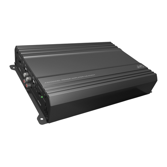
KS-AX204
POWER AMPLIFIER: INSTRUCTION MANUAL
LVT2505-001A [K]
2CAUTION
This unit is designed to operate on 12 V DC, NEGATIVE ground
electrical systems. JVC recommends consulting a qualified technician
for installation.
• To prevent short circuits while making connections, keep the
battery's negative terminal disconnected.
• This unit uses BTL (Balanced Transformerless) amplifier circuitry,
i.e., floating ground system, so comply with the following:
– Do not connect the "·" terminals of the speakers to each other.
– Do not connect the "·" terminals of the speakers to the metal
body or chassis.
• Cover the unused leads with insulating tape to prevent them from
short circuiting.
• If the fuse blows, first make sure the wires aren't touching to cause
a short circuit then replace the old fuse with one with the same
rating.
• This unit becomes very hot. Be careful not to touch the unit not
only when using but after using. DO NOT disassemble the unit
since there are no user serviceable parts inside.
• To keep the heat dissipation mechanism running effectively, wipe
the accumulated dust off periodically.
• Do not let pebbles, sand or metallic objects get inside the unit.
• Listening to the tape, radio, CD or digital audio player, etc. with
the volume set at a high level for a long period of time will exhaust
the battery, while the engine is turned off or while the engine is
idling.
• Use the speakers which have sufficient capacity to the unit.
INSTALLATION
INSTALLATION
The illustration above shows a typical installation. However, you
should make adjustments corresponding to your specific car.
Location of the unit
• Mount this unit on a firm surface, such as in the trunk or under the
front seat.
• When mounting the unit under the front seat, make sure that
adjusting the seat position will not catch any wire of the unit.
• Since heat is generated in the unit, do not mount it near
inflammable objects.
• Do not mount the unit in the places subject to heat: near a
radiator, in a glove compartment or in insulated areas such as
under a car mat that will prevent the unit from dissipating heat.
1 Under the front seat
2 Onto the trunk floor
Install the unit
• When mounting this unit, be sure to use the provided screws.
• If any other screws are used, there is a risk of loosening the unit or
damaging the parts under the car floor.
• Before drilling holes in the trunk to install the unit, make sure that
there is a sufficient space under the trunk so that you do not drill
holes in the fuel tank, etc.
3 Provided screw Ø 4 × 20 mm (13/16 in.)
4 Drilled hole
English
English
Advertisement

Summary of Contents for JVC KS-AX204
- Page 1 LVT2505-001A [K] English 2CAUTION This unit is designed to operate on 12 V DC, NEGATIVE ground electrical systems. JVC recommends consulting a qualified technician for installation. • To prevent short circuits while making connections, keep the battery’s negative terminal disconnected.
- Page 2 (The cross section is about 0.8 mm to 8 mm ¡ Connect to metallic body or chassis. ™-a When you use JVC car receiver with REMOTE OUTPUT, connect to REMOTE OUTPUT. ™-b When you use a unit without REMOTE OUTPUT, connect to the accessory circuit of the car which is activated by the ignition switch.
- Page 3 CONTROLS English CONTROLS POWER indicator The green lamp lights while the unit is turned on. CROSSOVER filter switch OFF: Normally set to this position. LPF: Set to this position when you want to turn on the LPF (Low-Pass Filter) switch. The Low Pass Filter transmits frequencies lower than 80 Hz.

