JVC EXAD KD-SHX855 Instructions Manual
Jvc cd/sd receiver instruction manual
Hide thumbs
Also See for EXAD KD-SHX855:
- Installation & connection manual (4 pages) ,
- Installation & connection manual (4 pages)

Related Manuals for JVC EXAD KD-SHX855


Summary of Contents for JVC EXAD KD-SHX855
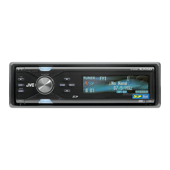
- Page 1 CD/SD RECEIVER For canceling the display demonstration, see page 9. For installation and connections, refer to the separate manual. INSTRUCTIONS KD-SHX855 KD-SHX855 SOURCE DISP BACK BAND PICT MENU LVT1373-001A KD-SHX855 [U, UH]...
-
Page 2: How To Reset Your Unit
Do not leave them in a car. Thank you for purchasing a JVC product. How to reset your unit This will reset the microcomputer. Your preset adjustments will also be erased. -
Page 3: Table Of Contents
Contents How to reset your unit ... How to read this manual ... How to forcibly eject a disc ... How to change the display pattern ... How to enter the various menus ... Control panel — KD-SHX855 Parts identification ... Remote controller —... -
Page 4: How To Read This Manual
How to read this manual The following methods are used to make the explanations simple and easy-to-understand: • Some related tips and notes are explained in “More about this receiver” (see pages 45 – 48). • Button operations are mainly explained with the illustrations as follows: Press briefly. -
Page 5: How To Change The Display Pattern
How to change the display pattern DISP Ex.: When tuner is selected as the source Source operation screen “Small” (CD jacket image) graphic “Large” (full screen size) graphic the display background. Graphic screen Audio level meters are displayed (see “LevelMeter” on page 37). Goes back to the initial display pattern. -
Page 6: Control Panel
Control panel — DISP BACK BAND PICT (angle) button Adjusts the control panel angle. 2 0 (eject) button Ejects the disc. 3 DISP (display) button Changes the information shown on the display. (standby/on/attenuator)/OK button • Turns on and off the power and also attenuates the sound. -
Page 7: Remote Controller
Remote controller — Installing the lithium coin battery (CR2025) • When operating, aim the remote controller directly at the remote sensor on the receiver. Make sure there is no obstacle in between. Warning: • Do not install any battery other than CR2025 or its equivalent;... -
Page 8: Getting Started
Getting started BACK BAND When activating or deactivating crossover network (see page 28), perform before turning on the power. Turn on the power. Ÿ SOURCE You cannot select some sources if they are not ready. For FM/AM tuner BACK BAND Basic operations SOURCE ⁄... -
Page 9: Canceling The Display Demonstration
Canceling the display demonstration If no operations are done for about 45 seconds, display demonstration starts. [Initial: Demo]—see page 37. Enter the PSM menu (see page 5). Select “Off.” • Make sure “Demo/Link” is shown on the display. If not, press 5 or ∞. Finish the procedure. -
Page 10: Radio Operations
Radio operations BACK BAND SOURCE Ÿ BACK BAND Preset number Current (if any) band Station frequency To assign names to the stations, see page 41. LO or DX indicator: See page 11. STEREO or MONO indicator: • STEREO indicator lights up when receiving an FM stereo broadcast with sufficient signal strength. -
Page 11: Storing Stations In Memory
Finish the procedure. indicator lights up. Reception improves, but stereo effect will be lost. To restore the stereo effect, repeat the same procedure and select “Off” in step 3. indicator goes off. To tune in FM stations only with strong signals—LO/DX (Local/ Distance-extreme) If received signals are weak, you may only hear noises. -
Page 12: Listening To A Preset Station
Manual presetting Ex.: Storing FM station of 92.5 MHz into preset number 3 of the FM1 band. SOURCE BACK BAND • If you hold 5/∞, the Preset Station List will appear (see step 7 below). Enter the MODE menu (see page 5). Select “List.”... -
Page 13: Disc/Sd Card Operations
Disc/SD card operations Playing a disc in the receiver All tracks will be played repeatedly until you change the source or eject the disc. About MP3 and WMA discs • When an MP3 or a WMA folder includes an image <jpw> file edited by Image Converter (Color Ver. -
Page 14: Playing Discs In The Cd Changer
About the CD changer It is recommended to use the JVC MP3- compatible CD changer with your receiver. • You can also connect other CH-X series CD changers (except CH-X99 and CH-X100). However, they are not compatible with MP3 discs, so you cannot play back MP3 discs. -
Page 15: Playing An Sd Card
About the SD card • When an MP3 or a WMA folder includes an image <jpw> file edited by Image Converter (Color Ver. 2.0)—supplied in the CD-ROM, you can show the image on the display while the tracks in the folder are played back—ImageLink. - Page 16 Attach the control panel. ⁄ • The control panel goes Current folder number Folder name Playback starts automatically if tracks are recorded. back to the previous position (see page 42). Current Elapsed track playing number time Track name If an SD card has been loaded... SOURCE Current Current...
-
Page 17: Other Main Functions
To fast-forward or reverse the track Fast-forwards. Reverses. To go to the next or previous tracks To the following tracks. To the beginning of the current track, then the previous tracks. To go to the next or previous folders (only for MP3 and WMA tracks) For MP3 tracks: For WMA tracks:... - Page 18 To start playback • Only for MP3: If you select the current disc (highlighted on the screen), its Folder List appears. When “Folder” is selected: Folder List appears. • You can move to the other lists by pressing 4/¢ ( To select a folder To start playback •...
-
Page 19: Selecting The Playback Modes
Prohibiting disc ejection You can lock a disc in the loading slot. After making sure “No Eject?” is selected (highlighted)... “No Eject” flashes, and the disc cannot be ejected. To cancel the prohibition Repeat the same procedure, press in step 2 after making sure that “Eject OK?” is selected (highlighted). - Page 20 Intro play Ex.: When “Track” is selected while playing an MP3 disc in the receiver Repeat play Ex.: When “Track” is selected while playing an MP3 disc in the receiver Random play Ex.: When “Disc” is selected while playing an MP3 disc in the receiver Only while playing an MP3 ( ) track.
-
Page 21: Sound Adjustments
Sound adjustments — Selecting the DSP modes —DSP You can create a more acoustic sound field such as in a theater, hall, etc. • When crossover network (see page 28) is activated, the DSP mode is fixed to “Defeat.” Available DSP modes Defeat (No acoustic effect is applied), Theater, Hall, Club, Dome, Studio, V.Cancel (Voice Cancel: Reduces the... - Page 22 To make further precise settings for the DSP modes Setting items: The number of the built-in speakers: Select the number of the speakers built in your car—“2ch” or “4ch.” Time alignment: Set the distance between each speaker and the listening seat position. Repeat steps select DSP mode.
-
Page 23: Making Sound Natural
Making sound natural To activate Compression Compensative (CC) Converter CC Converter eliminates jitter and ripples, achieving a drastic reduction in digital distortion. This processing can be applied to the analog sources as well as the digital sources; therefore, you can obtain a natural sound field from any source. -
Page 24: Using Equalizer-Eq
You can adjust the sound equalization patterns to your preference by using two EQ modes— Graphic EQ and Parametric EQ. Graphic EQ: You can select a preset sound mode suitable to the music genre. You can also store your own adjustments in memory. Parametric EQ: You can adjust the enhanced level, bandwidth, and center frequencies at three bands. -
Page 25: Selecting Preset Sound Modes
Selecting preset sound modes —Graphic EQ Available sound modes Flat (No sound mode is applied), Hard Rock, R&B (Rhythm&Blues), Pop, Jazz, Dance, Country, Reggae, Classic, User 1, User 2, User 3 • For User 1/2/3, you can store your own adjustment (see page 26). -
Page 26: Storing Your Own Sound Modes
Storing your own sound modes Follow steps ~ to ! on page 24. • In step Ÿ, select “Graphic.” Select a sound mode. Ex.: When “Flat” is selected Select the frequency band—63 Hz, 125 Hz, 250 Hz, 500 Hz, 1 kHz, 2 kHz, 4 kHz, 8 kHz, 12.5 kHz. -
Page 27: Adjusting Parametric Eq
Adjusting Parametric EQ Follow steps ~ to ! on page 24. • In step Ÿ, select “Parametric.” Select the band—Band1/2/3. Band1: Low band (20 Hz to 1.2 kHz) Band2: Mid band (80 Hz to 5 kHz) Band3: High band (315 Hz to 20 kHz) Adjust the enhanced level for the selected band within the range of –10 to +10. -
Page 28: Sound Adjustments
Sound adjustments — Activating crossover network Crossover network function enables to allocate sound signals to different speakers by frequency range. By activating crossover network, you can make precise adjustments to match the characteristic of each speaker. (See “To adjust reproduced frequency level—Crossover”... -
Page 29: Setting The Basic Sound Selection Menu-Sel
Setting the basic sound selection menu—SEL You can adjust the sound characteristics to your preference. Enter the SEL menu (see page 5). Ÿ Select a setting item—“Fad/Bal,” “Crossover ,” “Subwoofer,” or “VolAdjust.” Ex.: When “Fad/Bal” is selected * Appears only when crossover network is activated (see page 28). - Page 30 To adjust fader and balance —Fad/Bal Adjust the fader*—speaker output balance between the front and rear speakers. * When crossover network is activated, speaker output balance between high-range and mid- range speakers is adjusted. • F12: Upmost—front only • R12: Downmost—rear Adjust the balance—speaker output balance between the left and right speakers.
- Page 31 To adjust subwoofer output— Subwoofer To adjust subwoofer level Adjust the subwoofer output level. • 00 (min.) to 12 (max.) • Press to adjust reproduced frequency level and slope. To select the cutoff frequency Select an appropriate cutoff frequency level according to the subwoofer connected.
-
Page 32: Graphic Displays
Graphic displays Before starting the following procedure, prepare a CD-R or an SD card including still images (pictures) and animations (movies). • With Image Converter (Color Ver. 2.0) included in the supplied CD-ROM, you can create your own images and animations. (Samples are included in the CD-ROM.) •... -
Page 33: Downloading The Files
IMPORTANT: • Refer also to Image Converter PDF files included in the “Manual” folder on the supplied CD-ROM. • Still images (pictures) and animations (movie) should have the following extension code in their file names: – jpl: for large size still images –... -
Page 34: Deleting The Files
Download the file. • To cancel downloading, press DISP. • When download is complete, the File List appears again. • To download more pictures from the same folder, repeat steps 4 and • To download more pictures from another folder, press BACK. Then, repeat steps 3 to 5. - Page 35 • To delete the stored animation Ex.: When “Large” is selected for the picture size • When the animation is deleted, the PICT menu appears again. Finish the procedure. DISP Deleting all the stored pictures and animations for each size To delete all the stored pictures You can delete all stored pictures of each size (“Large”...
-
Page 36: Activating The Downloaded Files
Activating the downloaded files Enter the PSM menu (see page 5). Select “PICT.” Select the picture size you want to activate—“Large” or “Small.” * If there is no still images or animation downloaded, you can only select “Default.” Large Small Picture: One of your edited still images stored in “Picture”... -
Page 37: General Settings - Psm
General settings — PSM Basic procedure You can change PSM (Preferred Setting Mode) items listed in the table that follows. Enter the PSM menu (see page 5). Select a PSM item. Ex.: When “Scroll” is selected Indications Selectable settings, [reference page] Demo/Link Demo: Display... - Page 38 Indications Clock Hr Clock hour Clock Min Clock minute 24H/12H Clock system Scroll Scroll mode Dimmer Dimmer mode From–To* Dimmer time Bright Brightness Tag display Selectable settings, [reference page] 1 – 12 (0 – 23), [9] [Initial: 1 (1:00 AM)] 00 –...
- Page 39 Intermediate Wide: Subject to the interference noises from adjacent stations, but frequency filter Ext Input* Changer: [Initial]; To use a JVC CD changer, [14]. External input Ext Input: To use any external component other than above, [43]. Beep On: [Initial]; Activates the key-touch tone.
-
Page 40: Selecting The Dimmer Mode
Selecting the dimmer mode You can dim the display at night or as you set the timer. Enter the PSM menu (see page 5). Select “Dimmer.” Select a setting. Auto: Dims the display when you turn on the headlights. \ Go to step 6. Time Set: Sets the timer for dimmer. -
Page 41: Other Main Functions
Other main functions Assigning titles to the sources You can assign titles to station frequencies, CDs (both in this receiver and in the CD changer), and the external components. Sources Maximum number of characters Station Up to 16 characters (up to 30 frequencies station frequencies including both FM and AM) -
Page 42: Changing The Control Panel Angle
Changing the control panel angle The control panel changes its angle as follows: Angle 1 Angle 4 When using the remote controller... Caution: Do not insert your finger behind the control panel. When detaching or attaching the control panel, be careful not to damage the connectors on the back of the control panel and on the panel holder. -
Page 43: External Component Operations
External component operations Playing an external component SOURCE You can connect an external component to the LINE IN plugs on the rear. You can also connect an external component to the CD changer jack on the rear using the Line Input Adapter KS-U57 (optionally purchased) or Aux Input Adapter KS-U58 (optionally purchased). -
Page 44: Maintenance
Maintenance How to clean the connectors Frequent detachment will deteriorate the connectors. To minimize this possibility, periodically wipe the connectors with a cotton swab or cloth moistened with alcohol, being careful not to damage the connectors. Connector Moisture condensation Moisture may condense on the lens inside the CD player in the following cases: •... -
Page 45: More About This Receiver
More about this receiver Basic operations Turning on the power • By pressing SOURCE on the receiver, you can also turn on the power. Turning off the power • If you turn off the power while listening to a disc, disc play will start from where playback has been stopped previously, next time you turn on the power. - Page 46 Playing a CD-R or CD-RW • Use only “finalized” CD-Rs or CD-RWs. • This receiver can play back only the files of the same type which is first detected if a disc includes both audio CD (CD-DA) files and MP3/WMA files. •...
-
Page 47: Sound Adjustments — Daily Use
• This receiver cannot play back the following files: – MP3 files encoded with MP3i and MP3 PRO format. – MP3 files encoded in an unappropriated format. – MP3 files encoded with Layer 1/2. – WMA files encoded with lossless, professional, and voice format. - Page 48 Graphic displays General • You can display two sizes of pictures and animations (see page 5). – Large: <jpl> for the still pictures and <jpa> for the animations; The image can be shown as the display background. – Small: <jpm> for the still pictures and <jpb>...
-
Page 49: Troubleshooting
Troubleshooting What appears to be trouble is not always serious. Check the following points before calling a service center. Symptoms • Sound cannot be heard from the speakers. • The receiver does not work at all. • “Connect Error” appears on the display. - Page 50 Symptoms • “No Files” appears for a while, then the disc ejects. • Noise is generated. • Elapsed playing time is not correct. • “Not Support” appears on the display and track skips. • “No Music” appears on the display. •...
- Page 51 Symptoms • DSP mode cannot be selected other modes than “Defeat.” • Only high range sound or low range sound is reproduced though full range speakers are connected. • Download does not seem to finish. • The display graphic function does not work correctly.
-
Page 52: Specifications
Specifications AUDIO AMPLIFIER SECTION Maximum Power Output: Front: 70 W per channel Rear: 70 W per channel Continuous Power Output (RMS): Front: 35 W per channel into 4 Ω, 40 Hz to 20 000 Hz at no more than 0.8% total harmonic distortion. - Page 53 CD/SD PLAYER SECTION Type: Compact disc player Signal Detection System: Non-contact optical pickup (semiconductor laser) Number of Channels: 2 channels (stereo) Frequency Response: 5 Hz to 20 000 Hz Dynamic Range: 98 dB Signal-to-Noise Ratio: 102 dB Wow and Flutter: Less than measurable limit MP3 (MPEG Audio Layer 3): Max.
- Page 54 Having TROUBLE with operation? Please reset your unit Refer to page of How to reset your unit EN, TH © 2005 Victor Company of Japan, Limited 0405MNMMDWJEIN...
-
Page 55: Installation (In-Dash Mounting)
INSTALLATION (IN-DASH MOUNTING) The following illustration shows a typical installation. If you have any questions or require information regarding installation kits, consult your JVC car audio dealer or a company supplying kits. • If you are not sure how to install this unit correctly, have it installed by a qualified technician. -
Page 56: Electrical Connections
• Be sure to ground this unit to the car’s chassis again after installation. Notes: • Replace the fuse with one of the specified rating. If the fuse blows frequently, consult your JVC car audio dealer. • It is recommended to connect to the speakers with maximum power of more than 70 W (both at the rear and at the front, with an impedance of 4 Ω... - Page 57 µ√ß Ë « π ∑’ Ë ‰ ¡Ë ¡ ’ ’ ‡ §≈◊ Õ ∫ (À“°¡’ ’ ‡ §≈◊ Õ ∫Õ¬Ÿ Ë „ÀÈ ¢ Ÿ ¥ ’ Õ Õ°°Ë Õ π — Connecting cord supplied for your JVC CD changer µË Õ “¬∑’ Ë „ ÀÈ ¡ “ ”À√— ∫...
- Page 58 ’ ‡ ¢’ ¬ «·∂∫¥” °“√µË Õ ´— ∫ «Ÿ ‡ øÕ√ Connecting subwoofer / (‰¡Ë ‰ ¥È „ ÀÈ ¡ “°— ∫ ™ÿ ¥ ª√–°Õ∫π’ È ) JVC Amplifier ‡§√◊ Ë Õ ß¢¬“¬‡’ ¬ ß JVC Amplifier ‡§√◊ Ë Õ ß¢¬“¬‡’ ¬ ß...