Motorola APX 7000 User Manual
Hide thumbs
Also See for APX 7000:
- Detailed service manual (644 pages) ,
- Basic service manual (292 pages) ,
- User manual (213 pages)
Table of Contents
Advertisement
Quick Links
Advertisement
Table of Contents

Related Manuals for Motorola APX 7000


Summary of Contents for Motorola APX 7000
- Page 1 APX™ TWO-WAY RADIOS APX 7000/APX 7000L TOP DISPLAY USER GUIDE...
- Page 3 68007024033-G MOTOROLA, MOTO, MOTOROLA SOLUTIONS and the Stylized M logo are trademarks or registered trademarks of Motorola Trademark Holdings, LLC and are used under license. All other trademarks are the property of their respective owners. ©2009–2013 by Motorola Solutions, Inc. All Rights Reserved. 05/14.
- Page 4 Sending an Emergency Call Display Status Icons Basic Zone Bank 1 Press the Emergency button. A = Radio is in Zone 1. Blinks when the battery is low. B = Radio is in Zone 2. Press and hold the PTT button. Speak clearly C = Radio is in Zone 3.
-
Page 5: Table Of Contents
Contents Documentation Copyrights...15 Disclaimer........16 Declaration of Conformity......6 Important Safety Information..10 Getting Started....... 17 How to Use This Guide........17 Notations Used in This Manual......17 Software Version......11 Additional Performance Enhancement..17 Notice to Users (FCC and Industry ASTRO 25 Enhanced Data....17 Canada)............11 Dynamic System Resilience (DSR).. - Page 6 Attaching the Antenna........21 Selecting a Zone..........41 Removing and Attaching the Accessory Selecting a Radio Channel......41 Connector Cover........22 Receiving and Responding to a Radio Call... 41 Attaching the Belt Clip........23 Receiving and Responding to a Turning On the Radio........23 Talkgroup Call........41 Adjusting the Volume........24 Receiving and Responding to a...
- Page 7 Viewing a Scan List......48 Using TPS Emergency Viewing and Changing the Priority Transmission......... 56 Status..........48 Man Down............56 Scan...............48 Pre-Alert Timer........58 Turning Scan On or Off.......48 Post-Alert Timer........58 Making a Dynamic Priority Change Radio Alerts When Man Down (Conventional Scan Only)....48 Feature is Triggered......
- Page 8 Viewing the LTE Status.......80 Bluetooth Drop Timer......70 Utilities............82 Pairing with Low Frequency- Using the Flip Display......82 Motorola Proximity Pairing (LF- Selecting a Basic Zone Bank....82 MPP) Feature........ 71 Selecting an Enhanced Zone Bank..82 Radio Indications of Lost Bluetooth Selecting the Power Level....
- Page 9 Proper Ways to Handle the Radio..90 MOTOROLA COMMUNICATION Radio Service and Repair....91 PRODUCTS........... 104 Battery Care...........91 I. WHAT THIS WARRANTY COVERS Battery Charge Status......91 AND FOR HOW LONG:......104 Battery Recycling and Disposal..92 II. GENERAL PROVISIONS:....... 105 III.
-
Page 10: Declaration Of Conformity
Address: 1303 East Algonquin Road, Schaumburg, IL 60196-1078, U.S.A. Phone Number: 1-800-927-2744 Hereby declares that the product: Model Name: APX 7000/ APX 7000L conforms to the following regulations: FCC Part 15, subpart B, section 15.107(a), 15.107(d) and section 15.109(a) English... - Page 11 Class B Digital Device As a personal computer peripheral, this device complies with Part 15 of the FCC Rules. Operation is subject to the following two conditions: 1 This device may not cause harmful interference, and 2 This device must accept any interference received, including interference that may cause undesired operation. Note: This equipment has been tested and found to comply with the limits for a Class B digital device, pursuant to part 15 of the FCC Rules.
- Page 12 Conforms to the following regulations: FCC Part 15, Section 15.19, 15.21, and 15.105 Note: Changes or modifications not expressly approved by Motorola may void the users authority, as authorized by the FCC, to operate this device and should not be made. See 47 CFR Part 15.21. Information to the user. The user manual or instruction manual for an intentional or unintentional radiator shall caution the user that changes or modifications not expressly approved by the party responsible for compliance could void the user’s authority to...
- Page 13 If customers have already purchased the radio with the Bluetooth Option Board as part of the tanapa and they need to replace (repair) the option board, they can send the radio to any Motorola FM audited. English...
-
Page 14: Important Safety Information
Radios which contains important operating instructions for safe usage and RF energy awareness and control for Compliance with applicable standards and Regulations. For a list of Motorola-approved antennas, batteries, and other accessories, visit the following website: http://www.motorolasolutions.com/APX Under Industry Canada regulations, this radio... -
Page 15: Software Version
This device may not cause harmful interference. • This device must accept any interference received, including interference that may cause undesired operation. • Changes or modifications made to this device, not expressly approved by Motorola, could void the user's authority to operate this equipment. English... -
Page 16: Consignes De Sécurité Importantes
Cet émetteur radio a été approuvé par Industrie Canada pour utilisation avec une antenne approuvée Cette radio ne doit être utilisée qu'à des fins par Motorola offrant le gain maximal autorisé et professionnelles. Avant d'utiliser la radio, lisez le l'impédance requise pour le type d'antenne indiqué. Il... -
Page 17: Version Logicielle
Motorola, peuvent annuler le droit de l'utilisateur à Version logicielle utiliser cet équipement. Toutes les fonctions décrites dans les sections suivantes sont prises en charge par la version R13.00.00 ou les versions ultérieures du logiciel de la radio. Pour obtenir davantage de renseignements à propos des fonctions prises en charge, adressez-vous à... -
Page 18: Computer Software Copyrights
Motorola. Furthermore, the purchase of Motorola products shall not be deemed to grant either directly or by implication, estoppel, or otherwise, any license under the copyrights, patents or patent... -
Page 19: Documentation Copyrights
No duplication or distribution of this document or any portion thereof shall take place without the express written permission of Motorola. No part of this manual may be reproduced, distributed, or transmitted in any form or by any means, electronic or mechanical, for any purpose without the express written permission of Motorola. -
Page 20: Disclaimer
However, no responsibility is assumed for inaccuracies. Furthermore, Motorola reserves the right to make changes to any products herein to improve readability, function, or design. Motorola does not assume any liability arising out of the applications or use of any product or circuit described herein;... -
Page 21: Getting Started
Note: An operational procedure, practice, or condition Getting Started and so on, which is essential to emphasize. How to Use This Guide Additional Performance Enhancement The following performance enhancements are some This User Guide covers the basic operation of the of the latest creations designed to enhance the APX Portables. -
Page 22: Crosstalk Prevention
SecureNet allows user to perform secured Smart PTT is supported with this enhancement as communications on an Analog or Motorola Data Smart PTT prevents users from transmitting while Communication (MDC) channel. The MDC Over-the- other users are on the channel. -
Page 23: What Your Dealer/System Administrator Can Tell You
What Your Dealer/System Administrator Can Tell You Check with your dealer or system administrator for the correct radio settings, if the radio is to be operated in extreme temperatures (less than -30 °C or more than +60 °C), to ensure proper top and front display operation. -
Page 24: Preparing Your Radio For Use
Note: When charging a battery attached to a radio, turn the radio off to ensure a full charge. To charge the battery, place the battery (with or without the radio) in a Motorola-approved charger. The LED on the charger indicates the charging progress; see the charger user guide. -
Page 25: Attaching The Antenna
2 To remove the battery, squeeze the release latches at the bottom of the battery until the Attaching the Antenna battery releases from the radio and remove the battery from the radio. Ensure the radio is turned off before attaching the Note: When removing the battery, ensure that the antenna. -
Page 26: Removing And Attaching The Accessory Connector Cover
Note: To prevent damage to the connector, shield it with the connector cover when not in use. 1 To remove the accessory connector cover, rotate the thumbscrew counterclockwise until it disengages from the radio. Note: If the thumbscrew is too tight, use an Allen wrench at to loosen it first. -
Page 27: Attaching The Belt Clip
3 To attach the accessory connector cover, insert 2 Use a flat-bladed object to press the belt clip tab away from the radio. Then, slide the clip the hooked end of the cover into the slot above downward and away from the radio to remove the the connector. -
Page 28: Adjusting The Volume
• If the power-up test is successful, you see Adjusting the Volume momentary SELFTEST on the radio display, followed by the Home screen. Ensure the radio is power on and the main speaker is • If the power-up test is unsuccessful, you see pointed towards you for increased loudness and ERROR XX/YY (XX/YY is an alphanumeric intelligibility, especially in areas with loud background... - Page 29 2 To decrease the volume, rotate this knob counterclockwise. English...
-
Page 30: Identifying Radio Controls
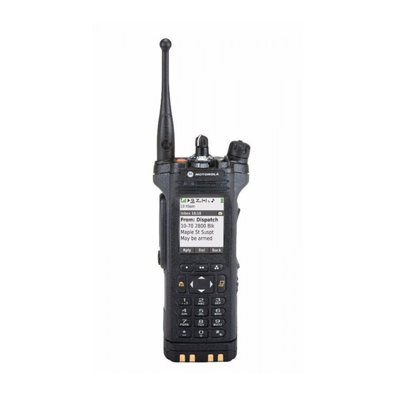
Identifying Radio Controls Radio Parts and Controls Antenna Top (Orange) Button Accessory Connector On/Off/Volume Control Knob English... -
Page 31: Programmable Features
3–Position A/B/C Switch Programmable Features 2–Position Concentric Switch Any reference in this manual to a control that is preprogrammed means that the control must be Belt Clip programmed by a dealer or qualified radio technician Battery Latch using the radio programming software, in order to assign a feature to that control. - Page 32 Remote Speaker Microphone cancels an emergency alarm or and Bluetooth headset. call. Bluetooth Keys up the Bluetooth Headset Internet Protocol Display the Internet Protocol Headset PTT microphone. Address (IP) address, device name and status of the radio. Bluetooth Clear Allows you to clear all pairing All Pairing information for Bluetooth.
- Page 33 One Touch 1– 4 Launches a specific feature Scan List Selects the scan list for editing with one single button-press. Programming (by long press on the Scan You can setup as many as four button). separately programmed buttons Secure Toggles the Secure for four different features.
-
Page 34: Assignable Settings Or Utility Functions
3 (A, B and C) to a second Volume Set Tone Sets the volume set tone. group of 3 zones (D, E and F). Accessing the Preprogrammed Functions Enhanced Zone Provides access from up to 75 Bank zones by toggling between 25 You can access various radio functions through the banks (A, B ... - Page 35 Press and hold down PTT button to talk. Release the PTT button to listen. The microphone is activated when the PTT button is pressed. • While a call is not in progress, the PTT button is used to make a new call. See Making a Radio Call on page 43 for more information.
-
Page 36: Identifying Status Indicators
Received Signal Strength Indicator Identifying Status Indicators (RSSI) Status Icons The number of bars displayed represents the received signal strength Selected icons are also shown on the first row of the for the current site, for trunking only. The 112 x 32 pixel top monochrome display screen of more stripes in the icon, the stronger the your radio. - Page 37 Power Level Basic Zone Bank 1 L – Radio is set at Low power. A – Radio is in Zone 1. H – Radio is set at High power. B – Radio is in Zone 2. C – Radio is in Zone 3. Scan Radio is scanning a scan list.
-
Page 38: Led Indicator
Y – Contains Zone 73, Zone 74 and Bluetooth is currently connected to the Zone 75. external Bluetooth device. Secure Operation LED Indicator Secure operation. The LED indicator shows the operational status of Clear operation. your radio. Blinking Receiving an encrypted voice call. -
Page 39: Intelligent Lighting Indicators
Rapidly blinking Radio has failed the self test Rapidly blinking Radio is on a Priority-One upon powering up or green channel while in the Scan List encountered a fatal error. Programming mode. Solid yellow Channel is busy. Note: No LED indication when the radio receives a (Conventional clear (non-secured) transmission in trunking Mode. - Page 40 Backlight and Bar Notification When Color Orange Emergency Alerts The radio initiates an emergency alarm or call. The radio receives an emergency alarm or call. Critical Alerts The radio battery is low. The radio is out of range. The radio enters Failsoft mode. The radio is unable to establish a full connection with the system.
-
Page 41: Alert Tones
Alert Tones Your radio uses alert tones to inform you of your radio’s condition. The following table lists these tones and when they occur. You Hear Tone Name Heard Short, Low- Radio Self Test Fail When radio fails its power-up self test. Pitched Tone Reject When an unauthorized request is made. - Page 42 You Hear Tone Name Heard Invalid Mode When radio is on an unpreprogrammed channel. A Group of Busy When system is busy. Low-Pitched Tones Short, Medium- Valid Key-Press When a correct key is pressed. Pitched Tone Radio Self Test Pass When radio passes its power-up self test.
- Page 43 You Hear Tone Name Heard Console Acknowledge When status, emergency alarm, or reprogram request ACK is received. Received Individual Call When Call Alert or Private Call is received. Site Trunking When a SmartZone trunking system fails. Short, High- Low-Battery Chirp When battery is below preset threshold value.
- Page 44 You Hear Tone Name Heard Bluetooth Connected When Bluetooth accessory is connected to the radio. Decremental- Bluetooth Unpaired When Bluetooth accessory is unpaired from the radio. Pitched Tone Bluetooth Disconnected When Bluetooth accessory is disconnected from the radio. A Group of Man Down Continuous When radio is in Man Down mode and prepares to transmit Very High-...
-
Page 45: General Radio Operation
a) Rotate the preprogrammed 16–Position General Radio Operation Select Knob to the desired channel. b) Press the PTT button to transmit on the Selecting a Zone displayed zone channel. Your radio must be preprogrammed to allow you to Receiving and Responding to a Radio Call use this feature. -
Page 46: Receiving And Responding To A Private Call (Trunking Only)
• For ASTRO Conventional system, the LED lights Note: With the inactivity timer enabled (optional), up solid yellow. The display shows the talkgroup when there is no response from the receiving radio, alias or ID, and the caller alias or ID. the transmitting radio exits the call with Menu Inactive Exit tone after the timer expires. -
Page 47: Making A Radio Call
Note: With the inactivity timer enabled (optional), if Making a Talkgroup Call there is no response to the call after the timer expires, To make a call to a group of users, your radio must your radio exits the call with Menu Inactive Exit tone. be configured as part of that talkgroup. -
Page 48: Switching Between Repeater Or Direct Operation Button
This digital technology quiets the transmission by Switching Between Repeater or Direct removing the noise from the signal and allows only Operation Button the clear voice or data information to be heard. The Repeater Operation increases the radio’s range Use the Monitor feature to make sure a channel is by connecting with other radios through a repeater. - Page 49 1 Momentarily press the Monitor button to listen for activity. The Carrier Squelch indicator appears on the display. 2 Press and hold the Monitor button to set continuous monitor operation. The duration of the button press is programmable. 3 Press the Monitor button again, or the PTT button, to return to the original squelch setting.
-
Page 50: Advanced Features
Responding to the Dynamic Regrouping Feature Advanced Features (Trunking Only) This feature allows the dispatcher to temporarily Advanced Call Features reassign selected radios to a particular channel where they can communicate with each other. This Selective Call (ASTRO Conventional Only) feature is typically used during special operations and This feature allows you to receive a call from a is enabled by a qualified radio technician. -
Page 51: Scan Lists
that you were using before the radio was dynamically channel, once the user has selected regrouped. the dynamic-regrouping position. Requesting a Reprogram (Trunking Only) Select Select-disabled radios cannot change This feature allows you to notify the dispatcher when Disabled channels while dynamically regrouped. you want a new dynamic regrouping assignment. -
Page 52: Viewing A Scan List
in your radio. These lists must be preprogrammed by One channel, regardless of traffic on non- a qualified radio technician. priority channels. • No icon indicates that the current channel is Viewing a Scan List deleted from the scan list. Turn the 16-Position Select Knob to view the members on the list. -
Page 53: Deleting A Nuisance Channel
This change remains in effect until scan is turned off. When the radio is locked onto the channel to be Scan then reverts to the preprogrammed (original) deleted, press the preprogrammed Nuisance setting. Delete button. Making a Dynamic Priority Change via the The radio continues scanning the remaining channels preprogrammed Dynamic Priority button: in the list. -
Page 54: Receiving A Call Alert Page
Receiving a Call Alert Page Only one of the Emergency modes above can be assigned to the preprogrammed Emergency button. When you receive a Call Alert page, you hear four repeating alert tones and the LED blinks green. The Note: To exit emergency at any time, press and hold the preprogrammed Emergency button for about a call received icons blinks and the display shows PAGE second. -
Page 55: Sending An Emergency Alarm
Man Down on page 56 for details. If no acknowledgement is received, the display shows NO ACK. The alarm ends and the radio exits the Sending an Emergency Alarm Emergency Alarm mode. This feature allows you to send a data transmission, Sending an Emergency Call (Trunking Only) which identifies the radio sending the emergency, to the dispatcher. -
Page 56: Sending An Emergency Alarm With Emergency Call
• You press the PTT button while in the 4 Release the PTT button to end the transmission Emergency Alarm mode. and wait for a response from the dispatcher. If unsuccessful, you hear the radio sounds a short 5 To exit Emergency Call, press and hold the low-pitched tone to indicate the selected channel preprogrammed Emergency button for about a does not support emergency and rejects to launch... -
Page 57: Change Of Channels During Emergency
state or change to a channel preprogrammed for 1 Press the preprogrammed Emergency button. Emergency. The display shows no changes, the LED does not light up, and you hear no tones. The silent Emergency Keep-Alive Feature emergency state continues until you perform the This feature, when enabled, prevents the radio from next step. -
Page 58: Entering Fireground Zone Channel
These components provide on-scene and inbuilding • Sending an Emergency Alarm and Call radio coverage, and enhanced personnel Entering Fireground Zone Channel accountability and monitoring. 1 Upon powering up, perform one of the following The radio helps to indicate your presence on the actions: scene if it is in the range of the Incident Commander command terminal. -
Page 59: Responding To Evacuation Indicator
the Volume Control Knob if necessary. • Move the Volume Control Knob to adjust the Release the Volume Set button. volume of the Evacuation Tone from full volume. • At the desired Fireground zone and channel, press the preprogrammed Monitor button and •... -
Page 60: Using Tps Emergency Transmission
• Receive and listen to call, the radio displays 2 Press PTT button to make Emergency Call. the caller’s name or ID. 3 Release to listen. Using TPS Emergency Transmission You hear Emergency Call De-Key Sidetone. After a short pause, you hear Emergency Beacon. The following are two important alert tones designed for this feature. - Page 61 radio motion below the motion sensitivity level, MAN-DOWN text on the screen. The Post-Alert Timer depending upon how the radio is programmed. The also initiates at this point. radio must stay in this condition for a preprogrammed 3 Man Down condition continues for the time amount of time before the Emergency Alarm or Call is duration defined in the Post-Alert Timer field.
-
Page 62: Pre-Alert Timer
If the radio is preprogrammed to horizontal only, it Exiting Man Down Feature on page 59 to exit must be worn in a vertical position otherwise the Man Man Down feature. Down alert may be inadvertently triggered. Radio Alerts When Man Down Feature is Triggered When the radio is programmed with Man Down The Man Down alert tone volume is directly related to feature, special care is required when charging the... -
Page 63: Radio Alerts When Man Down Enhanced Is Triggered
Note: At this point the Man Down features is Once the alert tone is active, changing to another complete. Use normal Emergency procedures to channel with different setup triggers a different cancel Emergency transmissions. response from the radio as described next. Radio Alerts When Man Down Enhanced is Triggered •... -
Page 64: Re-Initiating Man Down
Testing the Man Down Feature trunked and conventional channels. Enable the Emergency feature with Silent Alarm Unlike other forms of security, Motorola digital disabled, but not in Surveillance Mode before running encryption provides signaling that makes it virtually this test on the radio. -
Page 65: Selecting Clear Transmissions
button, you hear an invalid mode tone and the 1 Attach the KVL to your radio. display shows CLR TX. The display shows KEYLOAD, and all other radio functions, except for power down, backlight, and The radio will not transmit until you set the volume, are locked out. - Page 66 b) While holding Top Side (Select) button down, keys, operator-selectable keysets, press the Top (Orange) button. and operator-selectable key The display shows PLS WAIT. When all the erasure. If talkgroups are enabled encryption keys have been erased, the display in conventional, then the encryption shows ALL ERASED.
- Page 67 If the rekey operation fails, a bad-key tone sounds UKEK key, the radio could not be over the air and the display shows RKY FAIL. rekeyed. Note: The rekey operation failure indicates that Note: This feature must be preprogrammed by a qualified radio technician.
-
Page 68: Global Positioning System (Gps)
For example, GPS location fixes are very difficult to remains the same at obtain indoors, in covered locations, between high receiving radio. buildings, or in situations where you have not established a clear broad view of the sky. Random FM Reduces the unwanted effects of Once GPS is enabled, the radio displays the GPS Noise... -
Page 69: Gps Performance Enhancement
• Between tall buildings or under dense tree-cover GPS Performance Enhancement • In temperature extremes outside the operating Sometimes, the GPS feature may be unable to limits of your radio complete a location calculation successfully. You then see a message indicating that your radio cannot Even where location information can be calculated in connect to enough visible satellites. -
Page 70: Trunking System Controls
check with your nearest qualified technician for more Note: details. If the transmitting radio is stale at its location after a Note: If the receiving radio is operating in a Mixed period of time, the receiving radio display shows Mode channel, only if its voice transmission is via ID:<PTT ID>... -
Page 71: Out-Of-Range Radio
When the trunking system returns to normal The display shows the currently selected zone/ operation, your radio automatically leaves failsoft channel combination and STE TRNK. operation and returns to trunked operation. Note: When this occurs, you can communicate only To continue, in Failsoft, to communicate with other with other radios within your trunking site. -
Page 72: Mission Critical Wireless - Bluetooth
® Mission Critical Wireless - Bluetooth Personal Area Network (PAN) data profile. This feature allows your radio to extend its APX 7000L only works with Motorola MCW devices. functionality by connecting to external proprietary Turning the Bluetooth On Motorola accessories. -
Page 73: Turning The Bluetooth Off
If Bluetooth fails to launch, the display shows pairing keys. See Pairing with Low BT ON FL. Frequency-Motorola Proximity Pairing (LF-MPP) Feature on page 71 and Turning the Bluetooth Off Standard Pairing Feature on page 73. Turning the Bluetooth off via the preprogrammed Infinite (For all Bluetooth devices.) When the... -
Page 74: Bluetooth Drop Timer
Re-Pair Re-Pair Timer Scenarios Re-Pair Timer Description Timer Options Options Immediate 0 – 15 minutes programmable (For MCW buffer time to re-establish the and the user must re-pair the Accessories Bluetooth Connection when the devices. only) Bluetooth signal is out of range. •... -
Page 75: Pairing With Low Frequency-Motorola Proximity Pairing (Lf-Mpp) Feature
Pairing with Low Frequency-Motorola Proximity Pairing Re-Pair Timer Description (LF-MPP) Feature Options off. The radio and accessory will remain paired indefinitely. Once the device re-connect, the timer is reset. The radio could not control the Drop Timer of Personal Area Networking (PAN), Dial-Up Networking (DUN), Commercial Off- The-Shelf (COTS) and data services. - Page 76 radio) and the location of the receiver (your device or If the pairing process is successful, you hear an accessory). incremental-pitched tone. The radio begins to connect to the device. Obstacles that can cause an obstruction in the line-of- sight include trees, buildings, mountains, cars and If the pairing process fails, you hear a short, low- etc.
-
Page 77: Radio Indications Of Lost Bluetooth Connection
Bluetooth devices nearby. It is set to off by default. Standard Pairing Feature The radio only search for HSP devices and Motorola Note: Bluetooth tones, Bluetooth menu and MCW & OCW accessories. Radio will filter out other preprogrammed buttons must be preprogrammed by profiles. - Page 78 One of the following scenarios occurs: device is unpaired. The display shows <Device Type> UNPAIRED. • If successful, the display shows SRCH ON followed by SRCH END when the radio is pairing Turning Bluetooth Visibility On with a device found. The display shows Turning Bluetooth visibility to on enables other <Device Name>...
-
Page 79: Turning On The Bluetooth Audio (Routing The Audio From The Radio To The Headset)
a) Press the preprogrammed Bluetooth Audio Reroute button to route the audio from the Receiving Pairing Request from other Devices headset to the radio. A short, medium-pitched tone sounds. The display shows SPKR ON. Turn on your radio Bluetooth Visible mode. Your radio automatically accept the request and Adjusting the Volume of the Radio from Bluetooth pair with any request received from other device. -
Page 80: Clearing All Bluetooth Devices Information
Clearing All Bluetooth Devices Information data transfer without interrupting communication. The upgrade pauses to give priorities to voice call, and Clearing all Bluetooth devices information via the continues after the voice call ended. preprogrammed Bluetooth On/Off button: Once a configuration upgrade is downloaded to your a) Long press the preprogrammed Bluetooth radio, you can install new changes immediately or On/Off button. -
Page 81: Site Selectable Alerts (Astro 25)
Check with your agent if Voice Announcement is • Change to a new zone. The radio announces the available for the feature you need. current zone and channel it is transmitting. • Change to a new channel remaining within the The two options of priority for the Voice current zone. -
Page 82: Long Term Evolution (Lte)
Besides this, he remainder of the exterior is identical to APX 7000. Long Term Evolution (LTE) Note: Applicable for APX7000L only. The APX7000L enhances the current radio operation by providing the radio with faster information delivery over an LTE broadband network. -
Page 83: Data Profiles Available For Lte
Data Profiles Available for LTE System Operation Scenarios There are three different profiles available for LTE IV&D LTE and IV&D are mutually exclusive. data operation. Both systems cannot operate at the same time. Broadband Use only LTE data transmission Only network. -
Page 84: Turning On The Lte With Lte Button
reverts back to using LTE data The display shows LTE OFF to indicate the LTE transmission network. connection is off. Turning On the LTE with LTE Button Viewing the LTE Status Here are the definitions of the temporary statuses of Press and hold the preprogrammed LTE button. - Page 85 Status Derivation and definition Status Derivation and definition shown shown LTE HW currently LTE hardware There is an LTE alternating disconnected. error hardware error. with ERROR VPN AUTH LTE communication is Incorrect key alternating alternating disabled currently disabled on authentication installed for with with ERROR...
-
Page 86: Utilities
Perform the following action to see the temporary Use the preprogrammed Basic Zone Bank button status of LTE feature. to toggle the position between Bank 1 and Bank 2. The top display shows the status icons (A, B, C, D, Short press the preprogrammed button. -
Page 87: Selecting The Power Level
1 Press the preprogrammed EZB Up or EZB Down Use the preprogrammed Transmit Power Level button to scroll the EZB up or down or press and switch to toggle the power level between low and hold the preprogrammed EZB Up or EZB Down high power. -
Page 88: Locking And Unlocking The Controls
Locking and Unlocking the Controls and you hear a short tone, indicating that the feature is enabled. You can lock the programmable buttons, switches Using the Time-Out Timer and rotary knobs of your radio to avoid inadvertent entry. Check with your dealer or qualified technician This feature turns off your radio’s transmitter. -
Page 89: Using Conventional Squelch Operation Features
The time-out timer restarts and the LED lights up Option Result solid red. Digital Carrier-Operated You hear any digital Using Conventional Squelch Operation Features Squelch (COS) traffic. This feature filters out unwanted calls with low signal Normal Squelch You hear any digital strength or channels that have a higher than normal traffic having the correct background noise. -
Page 90: Digital Ptt Id Support
Note: When this feature is active, the Carrier inhibited. The LED lights up solid yellow to indicate Squelch status indicator is displayed. that the channel is busy. The following table shows the variations of smart Digital PTT ID Support PTT: This feature allows you to see the radio ID (number) Mode Description... -
Page 91: Transmit Inhibit
Transmit Inhibit Enabling Transmit Inhibition This feature is available for APCO 25 trunking, Type II Press the Transmit Inhibit programmable button. trunking and Conventional operations for all APX Note: If the user has disabled TX Inhibit via the radios. menu and then moves the switch to the position When Transmit Inhibit feature is enabled, the radio where TX Inhibit is enabled, the new value stops all transmission including voice and data. - Page 92 The display shows Tx inhibit off. You hear a sequence of short, high‐low tone (Transmit Inhibit Off tone) to indicate transmission is back to normal operation. English...
-
Page 93: Helpful Tips
• (For APX 7000/APX 7000L R Radios Only) Helpful Tips Your radio is designed to be submerged to a maximum depth of 6 feet, with a Radio Care maximum submersion time of 2 hours. Exceeding either maximum limit may result Caution: in damage to the radio. -
Page 94: Cleaning Your Radio
Caution: Do not use solvents to clean your Do not submerge the radio unless it is a radio as most chemicals may permanently ruggedized.(APX 7000/APX 7000L R model) damage the radio housing and textures. • Avoid subjecting the radio to corrosives, solvents Do not submerge the radio in the detergent or chemicals. -
Page 95: Radio Service And Repair
For a contract service agreement, • the LED blinks red when the PTT button is please contact your nearest Motorola service or sales pressed. representative, or an authorized Motorola dealer. •... -
Page 96: Battery Recycling And Disposal
11% to 25% 10% or less (at 10%, the gauge begins blinking) Battery Recycling and Disposal In the U.S. and Canada, Motorola participates in the nationwide Rechargeable Battery Recycling Corporation (RBRC) program for battery collection and recycling. Many retailers and dealers participate in this program. -
Page 97: Accessories
Accessories The accessory link below is for APX radios. Not all accessories are FCC certified to operate with all APX models and/or bandsplits. Please refer to the specific APX radio price pages for a list of FCC certified accessories or contact your sales representative for accessory compatibility. -
Page 98: Maritime Radio Use In The Vhf Frequency Range
• distance to a well-known landmark Maritime Radio Use in the VHF • vessel course, speed or destination Frequency Range 5 State the nature of the distress. 6 Specify what kind of assistance you need. Special Channel Assignments 7 State the number of persons on board and the number needing medical attention, if any. - Page 99 • on ships subject to Part II of Title III of the 156.050 160.650 Communications Act, the radio must be capable of 156.100 160.700 operating on the 156.800 MHz frequency. • on ships subject to the Safety Convention, the 156.150 160.750 radio must be capable of operating: 156.200...
- Page 100 156.900 161.500 156.325 160.925 156.950 161.550 67** 156.375 156.375 157.000 161.600 156.425 156.425 157.050 161.650 156.475 156.475 157.100 161.700 156.575 156.575 157.150 161.750 156.625 – 157.200 161.800 156.675 156.675 157.250 161.850 156.725 156.725 157.300 161.900 157.350 161.950 157.400 162.000 77** 156.875 –...
-
Page 101: Declaration Of Compliance For The Use Of Distress And Safety Frequencies
157.225 161.825 Technical Parameters for Interfacing External Data Sources 157.275 161.875 157.325 161.925 RS232 SB9600 157.375 161.975 Input 3.6V Voltage 157.425 162.025 (Volts Peak-to- Note: peak) * Simplex channels 3, 21, 23, 61, 64, 81, 82, and 83 Max Data 28 kb/s 12 Mb/s 9.6 kb/s... -
Page 102: Glossary
Feature that responds to the Automatic Registration Service presence of an RF carrier by opening or unmuting (turning ASTRO 25 Motorola standard for wireless on) a receiver’s audio circuit. A digital trunked communications. squelch circuit silences the ASTRO Motorola standard for wireless... - Page 103 operations of the trunked Digital Signal An RF signal that has a pulsed, repeaters. or discrete, nature, rather than a continuous nature. Channel A group of characteristics such as transmit/ receive frequency Dispatcher An individual who has radio pairs, radio parameters, and system management duties.
- Page 104 Post-Alert Timer is not cancelled. Key-variable loader: A device for loading encryption keys into Mission Critical Wireless the radio. Motorola Data Communication Liquid crystal display. Monitor Check channel activity by Light-emitting diode. pressing the Monitor button. If the channel is clear, you hear Li-Ion Lithium ion.
- Page 105 you hear conversation. It also Page A one-way alert, with audio serves as a way to check the and/or display messages. volume level of the radio, since Personality A set of unique features specific the radio “opens the squelch” to a radio. when the monitor button is pressed.
- Page 106 Radio Frequency The part of the general Status Calls Pre-defined text messages that (RF) frequency spectrum between allow the user to send a the audio and infrared light conditional message without regions (about 10 kHz to talking. 10,000,000 MHz). Tactical/ Non- The user talks on the channel Repeater A conventional radio feature,...
- Page 107 Unique Shadow Key. vpn1 Adapter name used by the radio for encrypted LTE traffic Zone A grouping of channels. English...
-
Page 108: Limited Warranty
MOTOROLA, at its option, will at no charge either Limited Warranty repair the Product (with new or reconditioned parts), replace it (with a new or reconditioned Product), or MOTOROLA COMMUNICATION PRODUCTS refund the purchase price of the Product during the warranty period provided it is returned in accordance with the terms of this warranty. -
Page 109: Ii. General Provisions
Because each FULL EXTENT SUCH MAY BE DISCLAIMED BY system which may use the Product is unique, LAW. MOTOROLA disclaims liability for range, coverage, or III. STATE LAW RIGHTS: operation of the system as a whole under this warranty. -
Page 110: What This Warranty Does Not Cover
MOTOROLA's normal warranty VI. PATENT AND SOFTWARE PROVISIONS: inspection and testing of the Product to verify any warranty claim. MOTOROLA will defend, at its own expense, any suit brought against the end user purchaser to the extent English... - Page 111 Product or parts MOTOROLA will have no liability with respect to any infringe a United States patent, and MOTOROLA will claim of patent infringement which is based upon the pay those costs and damages finally awarded against...
-
Page 112: Vii. Governing Law
This Warranty is governed by the laws of the State of Illinois, U.S.A. VIII. For Australia Only: This warranty is given by Motorola Solutions Australia Pty Limited (ABN 16 004 742 312) of Tally Ho Business Park, 10 Wesley Court. Burwood East, Victoria. - Page 114 Schaumburg, Illinois 60196 U.S.A. MOTOROLA, MOTO, MOTOROLA SOLUTIONS and the Stylized M logo are trademarks or registered trademarks of Motorola Trademark Holdings, LLC and are used under license. All other trademarks are the property of their respective owners. © 2009–2014 Motorola Solutions, Inc. All rights reserved.