
Related Manuals for Bryston SP1.7 Series


Summary of Contents for Bryston SP1.7 Series
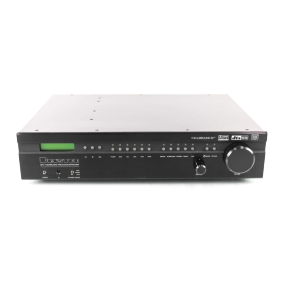
- Page 1 SP1.7 S E R I E S I N S T R U C T I O N S F O R B R Y S T O N S P 1 . 7 P R E C I S I O N...
- Page 2 Warranty coverage Is automatic and commences with the original date of manufacture which is kept on file at Bryston. In the event of a defect or malfunctIon, Bryston will remedy the problem by repair or replacement, as we deem necessary, to restore the product to full performance.
-
Page 3: Table Of Contents
Programming the AUX Trigger Output ....SP1.7 Remote Control ...... - Page 4 ACCESSORIES In the carton you should have found the following accessories in addition to the SP1.7: 1 Bryston SP1.7 Instruction Manual 1 Bryston Safety Manual 1 IEC standard power cord 1 SP1.7 Infrared Remote Control unit with backlight and battery installed It is VERY IMPORTANT that you read and completely understand the Bryston Safety Manual before installing or connecting the SP1.7 to any electrical power source.
- Page 5 {mains switch} is in the ON position. If the SP1.7 is to be unused for an extended period of time (i.e. a vacation) it is strongly recommended that it be turned off using the main power switch on the back panel.
-
Page 6: Front Panel Controls And Indicators
FRONT PANEL CONTROLS AND INDICATORS When looking at the front panel of the SP1.7 you will see the following controls and displays from left to right: Power [Momentary Switch] Toggling this switch up or down takes the unit in and out of its’... -
Page 7: Using The Dynamic Range Control
Contains the two line, black on green 16 character per line alphanumeric display which indicates the status and functional mode of the SP1.7. This screen is also used during the menu-setup function for calibration of the SP1 to your system. If connected to the Bryston SPV-1 Video Switcher, the menu-setup and status display will also be available on your video monitor with On-Screen Display (OSD). - Page 8 SP1.7’s analog and digital inputs to read the indicated source. TAPE TV/SAT If the SP1.7 is in its digital mode, as soon as any input is selected and switched, the decoder will automatically try to determine the new bitstream’s type and mode.
- Page 9 DIGITAL In this mode, the decoder will continually check the selected source inputs for the presence of a digital signal. If one is detected, the SP1.7 will auto- matically switch over to the pre-selected digital operation mode for that source.
- Page 10 If this button is selected and the supplied bitstream is more than 1 channel, the SP1.7 software will create a Mono mix of all signals. If the centre channel is present, the Mono signal will appear in the centre channel. If no centre channel is present, the mono signal will appear simultaneously on the Left/Right speakers.
- Page 11 12. THX Button Pressing this button will engage the SP1.7’s default THX listening mode. The default mode is selected using the “EX Control” menu (see page 26). NOTE: THX Surround EX™ decoding is only available in the THX listening mode.
- Page 12 Mode Button This button is used to select one of 13 effects for synthesizing surround sound with 2-channel source material. Pressing the button repeatedly will scroll through the modes: MODE You can select a Surround Mode for the Surround or THX listening modes at any time, even if the effect is not immediately active (such as the case when a 5.1 channel bitstream is present).
-
Page 13: Master Volume
Master Volume in all modes. It is fully motorized and can be operated from the remote control or by hand. It is the final level setting control on the SP1.7, and determines what output level will be supplied to the connected power amplifiers, but not the tape/recording outputs. It takes into... -
Page 14: Rear Panel Input And Output Connections
1. Balanced and 2. Unbalanced Outputs The SP1.7 offers both balanced (5.1) and unbalanced (7.1) outputs for power amplifiers or powered loudspeaker systems. The type you select to use will be determined by the input configuration of your amplifiers or self- powered loudspeakers. -
Page 15: Setting The Optical Input Assign
6. Tape/Recording Outputs The SP1.7 provides two analog outputs for the TAPE and VCR sources. The front panel selected input signal is always routed to these tape outputs, except when TAPE or VCR is selected. In those cases the appropriate output is automatically muted to prevent feedback. -
Page 16: Programming The Aux Trigger Output
IR receiver. 9. RS-232 connector This connection provides for control of a Bryston SPV-1 video switcher, or remote control of the SP1.7 functions via a computer interface or AMX/Crestron type controller. Please contact your dealer or Bryston to make use of this optional feature and determine which devices are compatible. -
Page 17: Sp1.7 Remote Control
6CH BYPASS button again. To use the Stereo Bypass mode for the currently selected source, press the 2CH BYPASS button. To go back to the previous selected mode, press the 2CH BYPASS button again. The SP1.7 from the Remote Control can operate all front panel operations, with the addition of several functions. -
Page 18: Mute Button
6. Test Button If pressed for more than 3 seconds, the SP1.7 will enter the Test/Noise mode. Please see Page 18 for more details on this mode. 7. Power Button Pressing this button will toggle the SP1.7 in and out of the Standby power mode. -
Page 19: Status Led
Press CODE button and release ii. LED will illuminate (Red) iii. Type in 3 digit code (a combination of mode buttons) iv. LED will flash again to confirm and go out. For a list of hidden codes, visit the Bryston Website at www.bryston.ca... -
Page 20: Setup And Calibration Of The Sp1.7
In order to fully enjoy the capabilities of the SP1.7 you or your dealer must first set-up and calibrate the SP1.7. This is a critical step in insuring that all your loudspeakers are properly designated within the unit and that all levels and delays are properly set. -
Page 21: Explanation Of 'Saved Settings Per Source
Explanation of ‘Saved Settings per Source’ Feature The SP1.7 will remember different mode settings for each source. Every time a source is engaged it will recall the following settings: Digital Status Listening Mode (Surround, THX, Stereo, Mono) Surround Mode Bypass Status... -
Page 22: Explanation Of 'Xtra Bass' Mode
The options available in this menu are: For LEFT/RIGHT (LR) you can select SMALL OR LARGE For CENTRE (C) you can select SMALL, LARGE or NONE FOR SURROUNDS (SUR) you can select SMALL, LARGE or NONE FOR BACK (BK) you can select NONE, ONE or TWO FOR SUBWOOFER (SUB) you can select YES or NO The SP1’s default factory settings as shipped are: Left/Right = LARGE... -
Page 23: Enabling The Subwoofer Output In The Bypass Mode
1. None: no subwoofer attached to the system. 2. Yes - Xbass Off: subwoofer is active, but only active with LFE tracks if the front speakers are full-range 3. Yes - Xbass On: subwoofer is active in system, in addition to full-range speakers. NOTE 1: the Xbass settings only show up in the menu if the front speakers are defined as ‘Large’. -
Page 24: Setting The Channel Delays
1. Now, make a measurement from the chosen seated position to each loudspeaker. 2. Next, enter the main menu by pressing on one of the menu buttons on the SP1.7 front panel. Move the cursor to “DLY”. Hit ‘Select’ - You are now in the Delay Menu. The SP1.7 automatically calculates the required delay time per speaker using the data entered as distance from the listening position. - Page 25 The sequence is L -> C -> R -> RS -> RB -> LB -> LS -> SUB -> EXIT. 4. Using the volume up/down arrows on the remote or the arrow keys on the SP1.7 adjust the level of the noise for each speaker so that it matches the front left channel noise (dB) level on the Sound Level Meter.
-
Page 26: Setting The Thx Subwoofer Limiter Or Bass Peak
1.`First enter the main menu by pressing on any one of the menu buttons on the SP1.7 front panel (< - > or SELECT). 2. Next move the cursor to “LVL”. Hit ‘SELECT’ - You are now in the Level Trim Menu. -
Page 27: Enabling Dts-Es 6.1 Decoding
3. Hit ‘SELECT’ and you will see the adjustment screen picture below appear, and you will hear a low level Pink Noise signal coming from your subwoofer and/or large speakers. Figure 21: BPLM Routine for level setting Now you can adjust the value of the subwoofer limiter (-24 to 0 dB). Slowly increase the level by pressing the “>”... -
Page 28: Enabling Thx Surround Ex™ Decoding
2. Next move the cursor to “OS”. Hit ‘SELECT’ – you are now in the ‘Other Settings’ menu. 3. Move the cursor to “ES”. Hit ‘SELECT’ – you can now change the ES Control setting. The options available in this menu are: DISABLE –... -
Page 29: Changing Dolby Plii Music Settings
3. Move the cursor to “EX”. Hit ‘SELECT’ – you can now change the EX Control setting. Figure 27: Change “EX” Control Setting The options available in this menu are: DISABLE – THX Surround EX™ will not be decoded ON – THX Surround EX™ will be forced on for all Dolby Digital 5.1 channel input bitstreams, if the back channels are enabled. - Page 30 PLII Film This is the preferred decoding method for watching movies with matrix surround encoding. The centre width and dimension variables are set and optimized for this application, and cannot be adjusted. No filters are present on the surround channels, and autobalance is operational. PLII Music This mode can enhance normal stereo music recordings, offering a wider soundstage and enhanced spatial effects.
-
Page 31: Changing Dts Neo:6 Settings
3. Move the cursor to the setting you want to change. The options are: CEN – center width (0 to 7; default 3) DIM – dimension (-3 to +3; default 0) PAN – panorama (YES or NO; default NO) Hit ‘SELECT’ – you can now change the chosen PLII setting. Figure 30: Change the PLII Centre Width Setting Changing DTS NEO:6 Settings Neo 6 provides up to six full-band channels of matrix decoding from stereo matrix material. - Page 32 To change the Center Image: 1. First enter the main menu by pressing on any one of the menu buttons (< - > or SELECT) 2. Next move the cursor to “DTS”. Hit ‘SELECT’ – you are now in the ‘DTS Settings’ menu. 3.
-
Page 33: Appendix A - Sp1.7 Surround Modes
Not all will supply something you may like, but there are so many variables that it does pay to take a few moments to listen to the options. The custom SP1.7 Surround Modes use a set of DSP algorithms to create a set of simulated signals using the original left and right 2 channel data and feeds these to the to centre and surround speakers. - Page 34 Party. The Party (Five-Channel Mono) Mode converts stereo input to a mono signal which is then distributed to the five satellite channels. Stereo5. The Stereo5 (Five-Channel Stereo) Mode converts stereo input to surround sound. The stereo signal is distributed to the five satellite channels, creating a giant stereo image in your listening space. (Please note that the apparent effect of the Surround Mode can be adjusted by altering the delay parameters and channel volume of the centre, surrounds and back channel(s), using the appropriate menus).
- Page 35 Table of all available surround modes. Signal Listening Surround Mode Effect DD 5.1 Surround DD 5.1 DD 5.1 DD 5.1 Stereo DD 5.1 Mono DTS 5.1 Surround DTS 5.1 DTS 5.1 Surround DTS 5.1 DTS 5.1 Stereo DTS 5.1 Mono DTS-ES Discrete Surround DTS-ES Discrete...
-
Page 36: Appedix B - Thx Information
THX website at WWW.THX.COM. When you choose the THX option for surround decoding modes within the SP1.7, by pressing the THX button on the front panel or the remote, an additional “post-processing” method is activated. The additional signal pro- cessing used in this mode is the result of extensive research, testing and refinement by the technical and engi- neering staff at LucasFilm, Ltd. -
Page 37: Example Hook-Up Diagram
OUTPUT OUTPUT OUTPUT OUTPUT 120W/8 120W/8S 120W/8 120W/8S FRONT LEFT LEFT SURROUND SINGLE BACK Figure 34 – SPV-1, SP1.7, 9B, and a 2ch9B or 3b Manufactured Manufactured XLR/PHONE XLR/PHONE Manufactured Manufactured XLR/PHONE XLR/PHONE PUSH PUSH under license under license INPUT... -
Page 38: Sp1.7 Specifications
SP1.7 SPECIFICATIONS Inputs Analog Audio: Six stereo (RCA) pairs, One 5.1 channel (RCA) input Digital: 4 coaxial (RCA) 75 Ohms, 2 Optical (TOSLINK?), conforms to S/PDIF standard. Pro version 1 AES/EBU input (XLR) 110 Ohms Infrared: 1 mini phone jack... -
Page 39: Suggested Surround Sound Placement
SUGGESTED SURROUND SPEAKER PLACEMENT Figure 35 – Suggested Surround Speaker Placement...