
Related Manuals for Bryston SP 1 Series


Summary of Contents for Bryston SP 1 Series
- Page 1 S P 1 S E R I E S I N S T R U C T I O N S F O R B R Y S T O N S P 1 P R E C I S I O N P R E A M P L I F I E R / P R O C E S S O R...
- Page 2 For more information, call us today or visit our web site, 1-800-632-8216, www.bryston.ca...
- Page 3 Your SP1 was carefully packed at the factory to protect against any damage in shipping and handling. Carefully examine the packing and the unit for any signs of external damage or impact and report those to your dealer or Bryston prior to using the unit. ACCESSORIES...
- Page 4 SP1 FUNCTIONAL LAYOUT Below is a block diagram of the Bryston SP1. It shows the signal flow and basic operational structure of the Surround Processor and Preamplifier. Figure 1: Block Diagram...
- Page 5 POWER The SP1 uses a dual mode electrical power system. In the electrical power input module located on the right hand side of the rear panel, adjacent to the IEC power cord socket is a large computer-style switch that controls the main electrical power to the unit.This is the ONLY switch that actually completely turns off all power to the unit.
-
Page 6: Front Panel Controls And Indicators
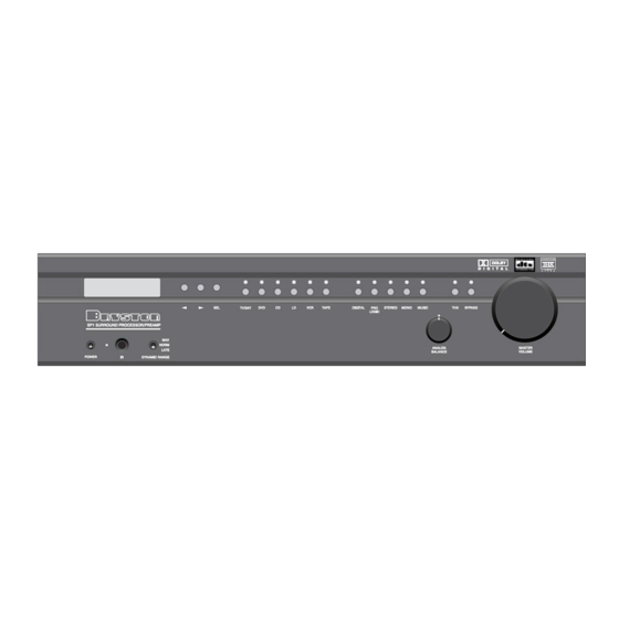
CONTROLS AND CONNECTIONS - OVERVIEW Front Panel Controls and Indicators Figure 3: Front Panel When looking at the front panel of the SP1 you will see the following controls and displays from left to right: 1. Power [Momentary Switch] Toggling this switch up or down takes the unit in and out of its' Standby power mode (see above) 2. - Page 7 A brief explanation follows: There are two variables built into many Dolby Digital bitstreams during the encoding process by the program producers, that can enable decoders like the SP1 to provide automatic gain control based upon the information supplied by these data variables. One of these two variables (labeled Dynrng by Dolby) provides a type of compression useful for situations such as late night viewing of programs with a wide dynamic range...
-
Page 8: Lcd Display Window
USING THE DYNAMIC RANGE CONTROL For the majority of applications this switch should be placed and remain in the middle or NORM position. For late night viewing or at any time you wish to reduce the overall dynamic range of a program the switch may be set to the "LATE"... - Page 9 6. Menu Control Buttons These three buttons labeled "<", ">", and "SEL" (SELECT) are used to control the menu/setup functions displayed on the LCD. To enter a menu mode, you can press any one of these buttons. This will bring up the main menu. All of the SP1 set-up and calibration operations are done using these buttons and the LCD screen.
-
Page 10: Mode Selection Buttons
Mode Selection Buttons: 8. Digital Mode and Indicator This button operates as a three way toggle function. The LED immediately above the button has two colors - RED and GREEN, and an OFF mode where it is not illuminated. When Digital Mode is selected, the decoder will automatically default to a digital signal for the selected input if one is present. -
Page 11: Music Modes
10. Stereo and Stereo Downmix Mode If this button is selected and the supplied bitstream is more than 2 channels, the decoder will automatically implement a stereo downmix. Otherwise, analog or digital two channel signals are passed as conventional stereo. 11. -
Page 12: Bypass Button
(LED illuminated) all of the DSP circuitry is bypassed, allowing a completely analog circuit path, identical to the reference standard Bryston BP-25 pre-amplifier. Only standard format Stereo operation is permitted in this mode - all other functions are disabled. -
Page 13: Analog Inputs
THE SP1 Rear Panel INPUT AND OUTPUT Connections Figure 6: Rear Panel 1. Balanced and 2. Unbalanced Outputs The SP1 offers both balanced and unbalanced outputs for power amplifiers or powered loudspeaker systems.The type you select to use will be determined by the input configuration of your amplifiers or self-powered loudspeakers. - Page 14 These can be used to control any Bryston Power amplifier and many other components such as motorized screens and drapes. Be sure to determine what type of trigger signal the selected components requires and what function will be enabled by the trigger signal's voltage.
- Page 15 This connection provides for control of an external video switcher, or remote control of the SP1 functions via a computer interface or AMX/Crestron type controller. Please contact your dealer or Bryston to make use of this optional feature and determine which devices are compatible. 10. IEC Power Connector 11.
- Page 16 SP1 will enter the Test/Noise mode. Please see Page 18 for more details on this mode. 6. Power Button Pressing this button will toggle the SP1 in and out of the Standby power mode. {Installers: please contact Bryston technical support for information about Discrete On/Off control}...
- Page 17 Bryston technical support BEFORE attempting this process. Most Bryston Dealers can provide this service. Please contact your dealer for their policies and procedures in this regard.
-
Page 18: System Setup And Configuration
System Setup and Configuration Setting the Speaker Configuration Before calibrating levels you must first tell the SP1 about your loudspeaker configuration.To do this: 1. First enter the main menu by pressing on any one of the menu buttons (< - > or SELECT). Figure 11: Setup Menu 2. -
Page 19: Setting The Channel Delays
to effectively handle the low frequency dynamics of modern motion picture soundtrack sources such as DVD or HDTV feeds, and many other discrete multi-channel programming sources. If in any doubt choose small, especially if you are using a subwoofer, since this will insure that all the appropriate low frequency information is directed to the subwoofer where it can be most effectively handled. - Page 20 Calibrating and Setting Levels / Channel to Channel Balance. 1. Position the Sound Level Meter at the Centre point of your listening area, at average ear height [ approximately 40 - 46 inches {102 - 117 cm.} with its microphone positioned vertically (pointing at the ceiling).
- Page 21 3. Move the cursor to the speaker(s) you want to change the level for using the arrow keys (L, C, R, RS, LS, SUB). Hit 'SELECT'. Now you can adjust the Level for the selected speaker using the arrow buttons. 4.
-
Page 22: Appendix A - Sp1 Music Modes
Setting the BPLM without Pink Noise To adjust the BPLM setting without running the Noise routine, Enter the BPLM as above, but when the SP1 prompts "Do BPLM Routine?", use the arrow keys to select ‘NO’ and hit ‘SELECT’. This will bring up the numeric value of the BPLM setting without the noise signal.You can now adjust the value using the arrow keys, and hit ‘SELECT’... - Page 23 to left surround and right to right surround, creating essentially a giant Stereo image throughout your space.The Music mode delay settings have no effect in this mode.This works especially well on lots of pop/rock music and also for many recordings with good natural ambiance. Natural: This mode enhances basic stereo reproduction by using the inherent acoustics recorded within the source material.
-
Page 24: Appendix B - Thx Information
APPENDIX B - THX INFORMATION Below is a summary of issues and information related to the proprietary and patented THX processing incorporated used in the SP1.The available space cannot include all the available information on this topic.Therefore, if you want more information or wish to research the topic in more detail please use the THX website at WWW.THX.COM.The information below was condensed from documentation... - Page 25 The SP1, contains special processing designed by THX to correct those errors and restore the appropriate tonal and spatial balance to a movie soundtrack, so that you can hear what the film's producer/director intended. This processing includes: 1. An Electronic Crossover Electronic Crossovers allow the use of the more typical residentially sized smaller main speakers by sending the bass signals to a separate subwoofer.
- Page 26 In a commercial Theatre, you don't detect this because the large number of surround speakers and the reflections within the room prevent your two ears from receiving equivalent signals. The THX Decorrelation Circuit discreetly changes the time and phase of one surround channel versus the other preventing your left and right ears from hearing identical signals, and helping to re-create the spacious and ambient sound you experience in a commercial Theatre.
- Page 27 Bryston. In the event of a defect or malfunction, Bryston will remedy the problem by repair or replacement, as we deem necessary, to restore the product to full performance.