Table of Contents
Advertisement
Advertisement
Table of Contents

Related Manuals for Elation CUEPIX BLINDER WW4


Summary of Contents for Elation CUEPIX BLINDER WW4
- Page 1 CUEPIX BLINDER WW4™ user manual ...
- Page 2 Elation Professional USA | 6122 S. Eastern Ave. | Los Angeles, CA. 90040 323-582-3322 | 323-832-9142 fax | www.elationlighting.com | info@elationlighting.com Elation Professional B.V.
-
Page 3: Table Of Contents
C O N T E N T S General Information Warranty Safety Instructions General Guidelines Fixture Overview Fixture Installation Understanding DMX Fixture Menu DMX Channel Functions And Values Cleaning and Maintenance Technical Specifications Optional Accessories CUEPIX BLINDER WW4™ User Manual Ver. 1... -
Page 4: General Information
Congratulations, you have just purchased one of the most innovative and ™ reliable lighting fixtures on the market today! The CUEPIX BLINDER WW4 been designed to perform reliably for years when the guidelines in this booklet are followed. Please read and understand the instructions in this manual carefully and thoroughly before attempting to operate this unit. - Page 5 You may also visit us on the web at www.elationlighting.com any comments or suggestions. For service related issue please contact Elation Professional®. ELATION SERVICE USA - Monday - Friday 8:00am to 5:00pm PST...
-
Page 6: Warranty
No accessories should be shipped with the product. If any accessories are shipped with the product, Elation Professional® shall have no liability what so ever for loss of or damage to any such accessories, nor for the safe return thereof. -
Page 7: Safety Instructions
. e l a t i o n l i g h t i n g . c o m S A F E T Y I N S T R U C T I O N S The CUEPIX BLINDER WW4™ is an extremely sophisticated piece of electronic equipment. To guarantee a smooth operation, it is important to follow the guidelines in this manual. -
Page 8: General Guidelines
• Use the original packaging and materials to transport the fixture in for service. DO NOT TOUCH the housing bare-hand during its operation. Turn OFF the power • and allow approximately 15 minutes for the fixture to cool down before replacing or serving. CUEPIX BLINDER WW4™ User Manual Ver. 1... -
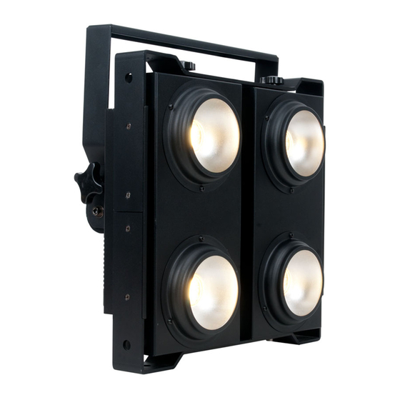
Page 9: Fixture Overview
5. ENTER Button 6. Fuse 7. powerCON IN 8. 3pin DMX IN 9. 5pin DMX IN 10.RJ45 NET IN 11.RJ45 NET OUT 12.3pin DMX OUT 13.5pin DMX OUT 14.powerCON OUT 15.Safety Cable Rigging Point CUEPIX BLINDER WW4™ User Manual Ver. 1... -
Page 10: Fixture Installation
The CUEPIX BLINDER WW4 provides an integrated yoke/rigging bracket. When mounting this fixture to truss be sure to secure an appropriately rated clamps to the yoke/rigging bracket using a M10 screw fitted through the center hole. CUEPIX BLINDER WW4™ User Manual Ver. 1... - Page 11 S A F E T Y C A B L E Always use a Safety Cable whenever installing this fixture in a suspended environment to ensure the fixture will not drop if the clamp fails. CUEPIX BLINDER WW4™ User Manual Ver. 1...
- Page 12 . e l a t i o n l i g h t i n g . c o m SECURING ™ Regardless of the rigging option you choose for your CUEPIX BLINDER WW4 always be sure to secure your fixture with a safety cable. The fixture provides a built-in rigging point for a safety cable on the base of the unit as illustrated below.
-
Page 13: Understanding Dmx
1 to that fixture no matter where it is located in the DMX chain. The CUEPIX BLINDER WW4™ can be controlled via DMX-512 protocol and the DMX address is set via the control menu. - Page 14 Connect the provided XLR cable to the female XLR output of your controller and the other side to the male XLR input of the CUEPIX BLINDER WW4™ The diagram below illustrates a typical DMX-512 connection when the fixture is in the 9 Channel Mode.
- Page 15 5pin XLR fixtures may be implemented in a 3pin XLR DMX line. When inserting standard 5pin XLR connectors in to a 3pin line a cable adaptor must be used, these adaptors are readily available at most electric stores. The following chart details a proper cable conversion. CUEPIX BLINDER WW4™ User Manual Ver. 1...
- Page 16 In the case of the CUEPIX BLINDER WW4™, when in the 9 Channel Mode you should set the starting DMX address of the first unit to 1, the second unit to 10 (1 + 9), the third unit to 19 (10 + 9), and so on.
-
Page 17: Fixture Menu
F I X T U R E M E N U ON-BOARD SYSTEM MENU The CUEPIX BLINDER WW4™ comes with an easy to navigate system menu. The next section will detail the functions of each command in the system menu. - Page 18 Fixture ID Set DMX Universe number. 000-255 Universe (Need to enter Service PIN to access this menu) Ethernet Set Kling-Net, ArtNet Set Protocol. Protocol Set Ethernet Set ON, OFF Set Network switch. Network Switch CUEPIX BLINDER WW4™ User Manual Ver. 1...
- Page 19 Speed00-99 Flash00-99 Speed & Flash Adjustable Chase 07.FLOW 2 Speed00-99 Flash00-99 Speed & Flash Adjustable Chase 08.FLOW 3 Speed00-99 Flash00-99 Speed & Flash Adjustable Chase 09.FLOW 4 Speed00-99 Flash00-99 Speed & Flash Adjustable CUEPIX BLINDER WW4™ User Manual Ver. 1...
- Page 20 . e l a t i o n l i g h t i n g . c o m FLIP SETTING Select the desired starting COB module and chase direction from one of the following modes below via UP/DOWN buttons and then press ENTER to confirm. CUEPIX BLINDER WW4™ User Manual Ver. 1...
- Page 21 IP Address, Subnet Mask, and the DMX Universe. This software application is Windows XP ™ and Windows 7 ™ compatible and is free of charge and available via download here. (See link below) http://artisticlicence.com/index.php?mode=products&sub=overview&action=&product_id=351 CUEPIX BLINDER WW4™ User Manual Ver. 1...
-
Page 22: Dmx Channel Functions And Values
PULSE Strobe Effect SLOW to FAST 160-191 COB ON 192-223 RANDOM Strobe SLOW to FAST 224-255 COB ON DIMMING CURVE MODES 0-20 STANDARD 21-40 STAGE 41-60 61-80 ARCHITECTURAL 81-100 THEATRE 101-255 Default to Unit Setting CUEPIX BLINDER WW4™ User Manual Ver. 1... -
Page 23: Cleaning And Maintenance
Regular inspections are recommended to insure proper function and extended life. There are no user serviceable parts inside this fixture, please refer all other service issues to an authorized Elation service technician. Should you need any spare parts, please order genuine parts from your local Elation dealer. -
Page 24: Technical Specifications
5°F to 113°F (-15°C to 45°C) APPROVALS / RATINGS CE | IP20 Please Note: Specifications and improvements in the design of this unit and this manual are subject to change without any prior written notice. CUEPIX BLINDER WW4™ User Manual Ver. 1... - Page 25 . e l a t i o n l i g h t i n g . c o m PHOTOMETRIC DATA DIMENSIONAL DRAWINGS Please Note: Specifications and improvements in the design of this unit and this manual are subject to change without any prior written notice. CUEPIX BLINDER WW4™ User Manual Ver. 1...
-
Page 26: Optional Accessories
3' (1m) powerCON PRO Link Cable PLC6 6' (1.8m) powerCON PRO Link Cable AC3PDMX5PRO 5 ft. (1.5m) 3pin PRO DMX Cable AC5PDMX5PRO 5 ft. (1.5m) 5pin PRO DMX Cable Additional Cable Lengths Available CUEPIX BLINDER WW4™ User Manual Ver. 1...