Sharp MD-MS701H Service Manual
Hide thumbs
Also See for MD-MS701H:
- Service manual (53 pages) ,
- Gebruiksaanwijzing (50 pages) ,
- Service manual (52 pages)
Table of Contents
Advertisement
Quick Links
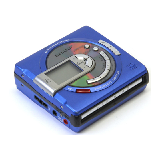
Illustration: MD-MS701H
SAFETY PRECAUTION FOR SERVICE MANUAL ............................................................................................................... 2
SPECIFICATIONS ................................................................................................................................................................. 3
NAMES OF PARTS ............................................................................................................................................................... 4
OPERATION MANUAL .......................................................................................................................................................... 5
DISASSEMBLY ...................................................................................................................................................................... 8
REMOVING AND REINSTALLING THE MAIN PARTS ......................................................................................................... 9
ADJUSTMENT ...................................................................................................................................................................... 10
NOTES ON SCHEMATIC DIAGRAM .................................................................................................................................. 28
BLOCK DIAGRAM ............................................................................................................................................................... 29
SCHEMATIC DIAGRAM/WIRING SIDE OF P.W.BOARD ................................................................................................... 30
WAVEFORMS OF CD CIRCUIT .......................................................................................................................................... 39
TROUBLE SHOOTING ........................................................................................................................................................ 40
FUNCTION TABLE OF IC .................................................................................................................................................... 43
PARTS GUIDE/EXPLODED VIEW
All manuals and user guides at all-guides.com
SERVICE MANUAL
CONTENTS
SHARP CORPORATION
- 1 -
MD-MS701H
MD-MS702H(BL)
MD-MS702H(GY)
• In the interests of user-safety the set should be restored to its original condition
and only parts identical to those specified should be used.
This document has been published to be used
for after sales service only.
The contents are subject to change without notice.
MD-MS701H/MS702H
No. SX789MDMS702H
Page
Advertisement
Table of Contents

Related Manuals for Sharp MD-MS701H


Summary of Contents for Sharp MD-MS701H
-
Page 1: Table Of Contents
MD-MS702H(BL) MD-MS702H(GY) • In the interests of user-safety the set should be restored to its original condition and only parts identical to those specified should be used. Illustration: MD-MS701H CONTENTS Page SAFETY PRECAUTION FOR SERVICE MANUAL ....................... 2 SPECIFICATIONS ................................. 3 NAMES OF PARTS ................................ -
Page 2: Safety Precaution For Service Manual
All manuals and user guides at all-guides.com MD-MS701H/MS702H SAFETY PRECAUTION FOR SERVICE MANUAL Precaution to be taken when replacing and servicing the Laser Pickup. The AEL (Accessible Emission Level) of Laser Power Output for this model is specified to be lower than Class I Requirements. -
Page 3: Specifications
FOR A COMPLETE DESCRIPTION OF THE OPERATION OF THIS UNIT, PLEASE REFER TO THE OPERATION MANUAL. SPECIFICATIONS General Weight: MD-MS701H: 216 g (0.48 lbs.) with Power source: DC 3.6 V (rechargeable lithium-ion rechargeable battery battery x 1) MD-MS702H: 219 g (0.49 lbs.) with... -
Page 4: Names Of Parts
All manuals and user guides at all-guides.com MD-MS701H/MS702H NAME OF PARTS Remote Control Unit 1. Synchro Recording Indicator 2. Character/Time Information Indicator SYNC 3. Record Indicator RANDOM 4. Repeat Indicator: TOTAL 5. Random Indicator 6. Disc Mode Indicator 7. Total Track Number Display 8. - Page 5 All manuals and user guides at all-guides.com MD-MS701H/MS702H – 5 –...
- Page 6 All manuals and user guides at all-guides.com MD-MS701H/MS702H – 6 –...
- Page 7 All manuals and user guides at all-guides.com MD-MS701H/MS702H – 7 –...
-
Page 8: Disassembly
All manuals and user guides at all-guides.com MD-MS701H/MS702H DISASSEMBLY Caution on Disassembly (A1)x2 Ø1.4x2mm Follow the below-mentioned notes when disassembling the unit and reassembling it, to keep it safe and ensure Pull (A1)x1 excellent performance: Ø1.4x2mm 1. Take the battery and minidisc out of the unit. -
Page 9: Removing And Reinstalling The Main Parts
All manuals and user guides at all-guides.com MD-MS701H/MS702H REMOVING AND REINSTALLING THE MAIN PARTS Remove the mechanism according to the disassembling meth- (A2)x3 ods 1 to 3. (See Page 8.) ø1.4x2.8mm How to remove the spindle motor (See Fig. 9-1.) 1. -
Page 10: Adjustment
All manuals and user guides at all-guides.com MD-MS701H/MS702H ADJUSTMENT Test disc MD adjustment needs two types of disc, namely recording disc (low reflection disc) and playback-only disc (high reflection disc). Type Test disc Parts No. High reflection disc MMD-110 (TEAC Test MD) - Page 11 All manuals and user guides at all-guides.com MD-MS701H/MS702H Operation in each TEST mode 1. AUTO1 Mode • When the STOP button is pressed while the AUTO1 menu appears or during automatic adjustment, the mode changes to the TEST mode stop state. At this time the adjustment value is not output.
- Page 12 All manuals and user guides at all-guides.com MD-MS701H/MS702H •Whenever the DISP button is pressed in the continuous playback mode, the indication changes as follows. * Pit section Continuous playback (SUBQ address indication) [ S Q Continuous playback (C1 error indication)
- Page 13 All manuals and user guides at all-guides.com MD-MS701H/MS702H 72h : EEPROM data read check sum error 73h : Record head drive disabled (by EJECT lever) 82h : Power overvoltage detection 91h : Ambient temperature is higher that the allowable temperature.
- Page 14 All manuals and user guides at all-guides.com MD-MS701H/MS702H [2] Temperature measurement value correction table Ambient temperature Temperature correction Center temperature C ~ +16 - 03h + 15.0 C ~ +19 - 02h + 17.8 C ~ +22 - 01h + 20.7 ±...
- Page 15 All manuals and user guides at all-guides.com MD-MS701H/MS702H -PROM DATA LIST TEMP setting Sled setting Item display Set values Item display Set values T M _ _ Calculate values S L G _ S L 2 _ BASS setting S L M _...
- Page 16 All manuals and user guides at all-guides.com MD-MS701H/MS702H – 16 –...
- Page 17 All manuals and user guides at all-guides.com MD-MS701H/MS702H – 17 –...
- Page 18 All manuals and user guides at all-guides.com MD-MS701H/MS702H – 18 –...
- Page 19 All manuals and user guides at all-guides.com MD-MS701H/MS702H – 19 –...
- Page 20 All manuals and user guides at all-guides.com MD-MS701H/MS702H – 20 –...
- Page 21 All manuals and user guides at all-guides.com MD-MS701H/MS702H – 21 –...
- Page 22 All manuals and user guides at all-guides.com MD-MS701H/MS702H – 22 –...
- Page 23 All manuals and user guides at all-guides.com MD-MS701H/MS702H – 23 –...
- Page 24 All manuals and user guides at all-guides.com MD-MS701H/MS702H – 24 –...
- Page 25 All manuals and user guides at all-guides.com MD-MS701H/MS702H – 25 –...
- Page 26 All manuals and user guides at all-guides.com MD-MS701H/MS702H – 26 –...
- Page 27 All manuals and user guides at all-guides.com MD-MS701H/MS702H – 27 –...
-
Page 28: Notes On Schematic Diagram
All manuals and user guides at all-guides.com MD-MS701H/MS702H NOTES ON SCHEMATIC DIAGRAM (CH), (TH), (RH), (UJ): Temperature compensation • Resistor: (ML): Mylar type To differentiate the units of resistors, such symbol as K and • The indicated voltage in each section is the one measured... -
Page 29: Block Diagram
All manuals and user guides at all-guides.com MD-MS701H/MS702H Figure 29 BLOCK DIAGRAM – 29 –... -
Page 30: Schematic Diagram/Wiring Side Of P.w.board
All manuals and user guides at all-guides.com MD-MS701H/MS702H P31 P32 MAIN PWB-A1 C112 0.033 C111 0.0033 R203 TP139 C109 C107 1/6.3 0.012 C131 C106 C211 330P(CH) 0.22/16 5P(CH) ROUT 48 47 46 45 44 43 42 41 40 39 38 37... - Page 31 All manuals and user guides at all-guides.com MD-MS701H/MS702H TP451 TP452 TP453 DADATA R455 R456 R457 TP454 ADDATA 5.6K 8.2K HKEY2 R458 TP455 DFCK TP456 R203 BCLK TP457 LRCK TP458 TP459 HREC C211 ADPON 5P(CH) HSTOP TP460 DAPON HPLAY TP461 OPTCNT...
- Page 32 All manuals and user guides at all-guides.com MD-MS701H/MS702H P30 P31 TP451 VOL UP TP452 VOL DOWN SKIP DOWN TP453 R455 R456 R457 TP454 SKIP UP 5.6K 8.2K R458 TP455 ENTER EDIT TP456 TP457 DISPLY TP458 C-MODE TP459 TP460 STOP TP461...
- Page 33 All manuals and user guides at all-guides.com MD-MS701H/MS702H IC101 IC201 IC202 IC401 IC402 IC501 IC601 IC651 NO. VOLTAGE NO. VOLTAGE NO. VOLTAGE NO. VOLTAGE NO. VOLTAGE NO. VOLTAGE NO. VOLTAGE NO. VOLTAGE NO. VOLTAGE NO. VOLTAGE 0.7V 1.0V 1.5V 2.5V 0.95V...
- Page 34 All manuals and user guides at all-guides.com MD-MS701H/MS702H DC IN J801 D800 BATTERY TERMINAL (+) R817 10 11 BATTERY TERMINAL (-) R818 C354 C603 C874 C353 Q352 R807 C805 L801 R808 C604 L600 R809 C808 C804 IC804 R801 C351 C806...
- Page 35 All manuals and user guides at all-guides.com MD-MS701H/MS702H P40 4-H FROM LCD FLEXIBLE PWB EXT. BATTERY TERMINAL C802 (220) TP801 MAIN PWB-A1 (BOTTOM) L887 TP805 TP806 TP803 15 14 P40 5-F P40 6-C Q801 FROM KEY FROM MECHA TP809 FLEXIBLE PWB (231)
- Page 36 All manuals and user guides at all-guides.com MD-MS701H/MS702H D491 L457 R767 R766 R768 R765 C752 IC703 J703 C767 HEADPHONES C755 R757 C762 R756 D494 Q711 C754 R761 C761 R714 C753 L491 R716 L702 R492 R715 C508 IC501 D492 C502 C713...
- Page 37 All manuals and user guides at all-guides.com MD-MS701H/MS702H JACK PWB-A2(BOTTOM) TP721 TP728 TP727 TP723 TP722 TP724 TP729 TP725 TP592 TP726 TP500 TP701 TP591 TP702 TP576 TP707 TP580 TP708 TP575 TP709 TP578 TP581 TP571 TP577 TP705 TP704 TP562 TP568 TP572 TP566...
- Page 38 All manuals and user guides at all-guides.com MD-MS701H/MS702H M901 M902 PICKUP UNIT (15) SPINDLE MOTOR SLED MOTOR M903 LIFT MOTOR SW901 DISC IN CN601 SW902 TO MAIN PWB DISC PROTECT P37 10-D MECHA FLEXIBLE PWB UNIT (8) CN101 TO MAIN PWB...
-
Page 39: Waveforms Of Cd Circuit
All manuals and user guides at all-guides.com MD-MS701H/MS702H WAVEFORMS OF MD CIRCUIT Stopped 1994 / 12 / 16 00:24:17 Stopped 1994 / 12 / 16 01:03:40 Stopped 1994 / 12 / 15 22:54:19 CH1=1mV CH2=500mV CH3=5V CH4=2V 50ms/div CH1=2V CH2=2V... -
Page 40: Troubleshooting
All manuals and user guides at all-guides.com MD-MS701H/MS702H TROUBLESHOOTING It is advisable to use the TEST mode (refer to Error Data Display Mode, P15) indicating the causes of troubles before starting repair. Causes of operation errors (up to 10 errors) are recorded as error codes. This information is useful for repair. - Page 41 All manuals and user guides at all-guides.com MD-MS701H/MS702H • Abnormal display Is waveform output from CNS 482 pins 1 to 3? Is waveform output from IC 401 pins 45 to 47? Are the pin7 (VCC) and pin 6 (GND) normal? Check between IC401 and Check the periphery of IC401.
- Page 42 All manuals and user guides at all-guides.com MD-MS701H/MS702H • The spindle motor fails to run.Does the head move Check the IC201 periphery. Does the waveform appear on the IC201 pins 24 and 25 after TEST mode AUTO2 completion and in this state? Replace.
-
Page 43: Function Table Of Ic
All manuals and user guides at all-guides.com MD-MS701H/MS702H FUNCTION TABLE OF IC IC401 RH-iX2680AF03(IX2680AF):System Microcomputer (1/2) Port Name Terminal Name Input/Output Function Pin No. P120 SWP UP Output Asterisk input Output for pull-up 2*~7* P121~P126 P121~P126 Output Not used P127... - Page 44 All manuals and user guides at all-guides.com MD-MS701H/MS702H IC401 RH-iX2680AF03(IX2680AF):System Microcomputer (2/2) Port Name Terminal Name Input/Output Function Pin No. LDON Output P.U. laser ON/OFF control output OPICGA Output P.U. detection sensitivity selection output RFLAT Output RF amp. IC data latch output...
- Page 45 “HOW TO ORDER REPLACEMENT PARTS” To have your order filled promptly and correctly, please furnish the For U.S.A. only following information. Contact your nearest SHARP Parts Distributor to order. 1. MODEL NUMBER 2. REF. No. 3. PART NO. 4. DESCRIPTION For location of SHARP Parts Distributor, Please call Toll-Free;...
- Page 46 All manuals and user guides at all-guides.com MD-MS701H/MS702H PRICE PRICE PART CODE DESCRIPTION PARTS CODE DESCRIPTION RANK RANK INTEGRATED CIRCUITS AC 10 µH,Choke L171 RCILC0333AFZZ AC 0.47 µH L201 VPBNNR47M0000 AC 10 µH IC101 VHIIR3R55//-1 AQ RF Signal,Processor,IR3R55 L202 VPBNN100M0000...
- Page 47 All manuals and user guides at all-guides.com MD-MS701H/MS702H PRICE PRICE DESCRIPTION PARTS CODE DESCRIPTION PART CODE RANK RANK RESISTORS AE 15 µF,10V,Electrolytic,Tantalum C600 VCSAFB1AJ156M AC 1 µF,6.3V,Electrolytic C601~604 RC-KZ1193AFZZ AD 3.3 µF,10V,Electrolytic C608 RC-KZ1216AFZZ VRS-CY1JB000J AA 0 ohm,Jumper,0.8×1.55mm, AC 1 µF,6.3V,Electrolytic...
- Page 48 All manuals and user guides at all-guides.com MD-MS701H/MS702H PRICE PRICE PART CODE DESCRIPTION PARTS CODE DESCRIPTION RANK RANK R810,811 VRS-CY1JB184D AA 180 kohms,1/16W NGERH0595AFZZ AC Gear,Lift Drive R814,815 VRS-CY1JB392D AA 3.9 kohms,1/16W MLEVF2600AFFW AD Lever,Lift R816 VRS-CY1JB122D AA 1.2 kohms,1/16W...
- Page 49 All manuals and user guides at all-guides.com MD-MS701H/MS702H PRICE PRICE DESCRIPTION PARTS CODE DESCRIPTION PART CODE RANK RANK PSPAZ0532AFZZ AC Spacer Mechanism PSHET0375AFZZ AB Sheet,LCD HDECB0458AFSA AB Decoration Screw [702H Only] HDECQ0530AFSA J AL Decoration Ring [702H GY] HDECQ0530AFSB J...
- Page 50 All manuals and user guides at all-guides.com MD-MS701H/MS702H (SW902) (SW901) 503x2 M901 M902 M903 511x2 Figure 5 MD MECHANISM EXPLODED VIEW – 5 –...
- Page 51 All manuals and user guides at all-guides.com MD-MS701H/MS702H 221-2 221-4 MD Mechanism MS702H Only 241x3 221-3 221-5 221-1 610x2 PWB–A2 MS702H MS701H 608x2 PWB–A1 608x2 202-4 202-1 202-2 610x2 202-3 610x2 Figure 6 CABINET EXPLODED VIEW – 6 –...
-
Page 52: Packing Method (For Uk Only)
14. SPAKZ0475AFZZ Pad, Operation Manual 15. SPAKZ0479AFZZ Sheet MD-MS701H © COPYRIGHT 1997 BY SHARP COPORATION ALL RIGHTS RESERVED. SHARP CORPORATION Audio-Visual Systems Group Quality & Reliability Control Center No part of this publication may be reproduced, Higashihiroshima, Hiroshima 739-01, Japan stored in a retrieval system, or transmitted in Printed in U.K.