Table of Contents
Advertisement
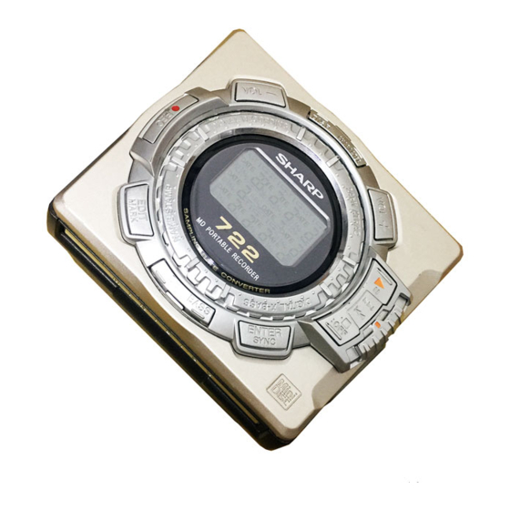
(Illustration: MD-MS722/MS722C/MS722W)
SAFETY PRECAUTION FOR SERVICE MANUAL (MD-MS722W/MS721W ONLY) ............................................................ 2
SPECIFICATIONS ................................................................................................................................................................. 3
NAMES OF PARTS ............................................................................................................................................................... 4
OPERATION MANUAL .......................................................................................................................................................... 6
QUICK GUIDE (MD-MS722 ONLY) ....................................................................................................................................... 9
DISASSEMBLY .................................................................................................................................................................... 11
INSTALLING THE TOP CABINET ....................................................................................................................................... 11
REMOVING AND REINSTALLING THE MAIN PARTS ....................................................................................................... 12
ADJUSTMENT ...................................................................................................................................................................... 13
BLOCK DIAGRAM ............................................................................................................................................................... 29
SCHEMATIC DIAGRAM/WIRING SIDE OF P.W.BOARD ................................................................................................... 30
NOTES ON SCHEMATIC DIAGRAM .................................................................................................................................. 39
WAVEFORMS OF MD CIRCUIT ......................................................................................................................................... 40
TROUBLE SHOOTING ........................................................................................................................................................ 41
FUNCTION TABLE OF IC .................................................................................................................................................... 44
PARTS GUIDE/EXPLODED VIEW
SERVICE MANUAL
(Illustration: MD-MS721W)
CONTENTS
SHARP CORPORATION
MD-MS722
MD-MS722C
MD-MS722W
MD-MS721W(BL)
MD-MS721W(S)
• In the interests of user-safety the set should be restored to its
original condition and only parts identical to those specified be
used.
This document has been published to be used
for after sales service only.
The contents are subject to change without notice.
- 1 -
MD-MS722/C/W/MS721W
No. SX891MDMS722U
Page
Advertisement
Table of Contents

Related Manuals for Sharp MS722 - MiniDisc Recorder - Metallic


Summary of Contents for Sharp MS722 - MiniDisc Recorder - Metallic
-
Page 1: Table Of Contents
FUNCTION TABLE OF IC ..............................44 PARTS GUIDE/EXPLODED VIEW PACKING OF THE SET (MD-MS722 ONLY) This document has been published to be used SHARP CORPORATION for after sales service only. The contents are subject to change without notice. – 1 –... -
Page 2: Safety Precaution For Service Manual (Md-Ms722W/Ms721W Only)
MD-MS722/C/W/MS721W SAFETY PRECAUTION FORSERVICE MANUAL (MD-MS722W/MS721W ONLY) Precaution to be taken when replacing and servicing the CAUTION Laser Pickup. The AEL (Accessible Emission Level) of Laser Power Output for this model is specified to be lower than Class I Require- ments. -
Page 3: Specifications
MD-MS722/C/W/MS721W FOR A COMPLETE DESCRIPTION OF THE OPERATION OF THIS UNIT, PLEASE REFER TO THE OPERATION MANUAL. SPECIFICATIONS General Output level: Specified Maximum Load Power source: DC 3.6 V (rechargeable lithium-ion (MS722/MS722C) output output level impedance (MS722/MS722C) battery x 1) Headphones —... -
Page 4: Names Of Parts
MD-MS722/C/W/MS721W NAME OF PARTS MD-MS722/MS722C/MS722W Remote control unit 1. Synchro Recording Indicator SYNC 2. Character/Time Information Indicator RANDOM TOTAL 3. Record Indicator 4. Repeat Indicator: 5. Random Indicator 6. Disc Mode Indicator 7. Total Track Number Display 8. Track Number Indicator 9. - Page 5 MD-MS722/C/W/MS721W MD-MS721W Remote control unit 1. Synchro Recording Indicator SYNC 2. Character/Time Information Indicator RANDOM TOTAL 3. Record Indicator 4. Repeat Indicator: 5. Random Indicator 6. Disc Mode Indicator 7. Total Track Number Display 8. Track Number Indicator 9. Battery Indicator: 10.
-
Page 6: Operation Manual
MD-MS722/C/W/MS721W OPERATION MANUAL OPEN OPEN – 6 –... - Page 7 MD-MS722/C/W/MS721W – 7 –...
- Page 8 MD-MS722/C/W/MS721W – 8 –...
-
Page 9: Quick Guide (Md-Ms722 Only)
MD-MS722/C/W/MS721W QUICK GUIDE (MD-MS722 ONLY) OPEN OPEN OPEN – 9 –... - Page 10 MD-MS722/C/W/MS721W – 10 –...
-
Page 11: Disassembly
MD-MS722/C/W/MS721W DISASSEMBLY (A2)x2 ø1.4x2mm (A2)x1 Cares before disassembling ø1.4x2mm (B1)x1 When assembling the machine after disassembling or Bottom Cabinet ø1.4x2mm repair, observe the following requirements so as to (A2)x1 ø1.4x2.5mm (A1)x1 ensure safety and performance. 1. Remove the batteries from the machine, and take out the mini-disc. -
Page 12: Removing And Reinstalling The Main Parts
MD-MS722/C/W/MS721W REMOVING AND REINSTALLING THE MAIN PARTS Remove the mechanism according to the disassembling meth- (A2)x3 ø1.4x2.8mm ods 1 to 3. (See Page 11.) How to remove the spindle motor (See Fig. 12-1.) Spindle Motor 1. Remove the solder joint (A1) x 1 of flexible PWB. 2. -
Page 13: Adjustment
MD-MS722/C/W/MS721W ADJUSTMENT Test disc MD adjustment needs two types of disc, namely recording disc (low reflection disc) and playback-only disc (high reflection disc). Type Test disc Parts No. High reflection disc MMD-110 (TEAC Test MD) 88GMMD-110 Lowreflection disc MMD-212 (TEAC Test MD) 88GMMD-212 Low reflection disc Recording minidisc... - Page 14 MD-MS722/C/W/MS721W Operation in each TEST mode 1. AUTO1 Mode • When the STOP button is pressed while the AUTO1 menu appears or during automatic adjustment, the mode changes to the TEST mode stop state. At this time the adjustment value is not output. •...
- Page 15 MD-MS722/C/W/MS721W •Whenever the DISP button is pressed in the continuous playback mode, the indication changes as follows. * Pit section Continuous playback (SUBQ address indication) [ S Q Continuous playback (C1 error indication) [ C E Continuous playback (SUBQ address indication) [ S Q * Groove section Continuous playback (ADIP address indication)
- Page 16 MD-MS722/C/W/MS721W 13. INNER Mode • when the STOP button is pressed on the INNER menu (SQ______ ), the state is changed to the TEST mode STOP state. • : Address EEPROM (IC402) writing procedure 1. Procedure to replace EE-PROM and write initial value of microcomputer in EEPROM (1) Replace EEPROM.
- Page 17 MD-MS722/C/W/MS721W EEPROM DATA LIST (EEPROM version f) Sled setting TEMP setting Item display Set values Item display Set values S L G _ T M _ _ Calculate values S L 2 _ Fucus setting S L M _ Item display Set values S L V _ F G _ _...
- Page 18 MD-MS722/C/W/MS721W – 18 –...
- Page 19 MD-MS722/C/W/MS721W – 19 –...
- Page 20 MD-MS722/C/W/MS721W – 20 –...
- Page 21 MD-MS722/C/W/MS721W – 21 –...
- Page 22 MD-MS722/C/W/MS721W – 22 –...
- Page 23 MD-MS722/C/W/MS721W – 23 –...
- Page 24 MD-MS722/C/W/MS721W – 24 –...
- Page 25 MD-MS722/C/W/MS721W – 25 –...
- Page 26 MD-MS722/C/W/MS721W – 26 –...
- Page 27 MD-MS722/C/W/MS721W – 27 –...
- Page 28 MD-MS722/C/W/MS721W – 28 –...
-
Page 29: Block Diagram
MD-MS722/C/W/MS721W +2.5 AVCC Figure 29 BLOCK DIAGRAM – 29 –... -
Page 30: Schematic Diagram/Wiring Side Of P.w.board
MD-MS722/C/WMS721W P31 P32 MAIN PWB-A C112 0.033 PLAYBACK SIGNAL C111 TP202 0.0033 C110 RECORD SIGNAL TP139 C107 0.22 C109 0.012 L204 R207 XL201 1/16 C106 0.22 33.8688MHz CK207 48 47 46 45 44 43 42 41 40 39 38 37 R106 ADAGC ROUT... - Page 31 MD-MS722/C/W/MS721W DADATA HREC ADDATA DFCK TP202 BCLK LRCK JOG0 TP139 JOG1 L204 R207 XL201 ADPON R460 33.8688MHz R455 R456 R457 DAPON 5.6K 8.2K OPTCNT HKEY2 R459 CK207 HSTOP C212 TP211 8P(CH) TP212 TP205 EMPH1 HPLAY C204 0.47 HKEY1 R451 R452 R453 R454 5.6K...
- Page 32 MD-MS722/C/WMS721W KEY FLEXIBLE PWB UNIT FLEXIBLE DISPLAY TP451 TP452 VOL DOWN HREC TP453 TP454 EDIT TP455 P-MODE TP456 JOG0 TP457 JOG 1 JOG 2 JOG1 TP458 R460 TP459 R456 R457 R455 5.6K 8.2K HKEY2 R459 TP461 BASS TP462 ENTER HSTOP TP463 STOP TP464...
- Page 33 MD-MS722/C/W/MS721W IC101 IC200 IC401 IC501 IC701 IC820 VOLTAGE VOLTAGE VOLTAGE VOLTAGE VOLTAGE VOLTAGE VOLTAGE VOLTAGE 0.7V 2.35V 2.5V 1.25V 0.7V 2.5V 2.48V 2.5V 1.2V 0.7V 1.27V 2.35V 0.96V 0.7V 2.33V 1.29V 1.27V 2.33V 0.95V 1.26V 1.27V 0.7V 3.55V 1.27V 2.35V 1.26V 1.27V 2.35V...
- Page 34 MD-MS722/C/WMS721W (Only Serial No. 81101800) J703 REMOTE CONTROL/ J801 HEADPHONES DC IN R800 C804 J702 R809 MIC IN D802 R893 R727 R801 Q892 C725 Q721 C805 R804 IC801 D801 C726 R726 C727 L704 C872 L871 Q891 D861 L862 C807 IC802 F800 C806 L851...
- Page 35 MD-MS722/C/W/MS721W P38 6 - H TP721 TP729 TP726 TP722 D491 C491 TP711 D493 TP802 TP713 L713 L457 L452 C751 L453 L458 C800 L711 TP714 TP805 L456 TP728 TP727 L454 TP801 C752 L714 TP772 TP725 TP484 R482 C703 TP724 C702 IC841 BATTERY,–...
- Page 36 MD-MS722/C/WMS721W (From Serial No. 81201801) J703 REMOTE CONTROL/ J801 HEADPHONES DC IN R800 C804 J702 R809 MIC IN D802 R893 R727 R801 Q892 C725 Q721 C805 R804 IC801 D801 C726 R726 C727 L704 C872 L871 Q891 D861 L862 C807 IC802 F800 C806 L851...
- Page 37 MD-MS722/C/W/MS721W P38 6 - H TP721 TP729 TP726 TP722 D491 C491 D493 TP711 TP802 TP713 L713 L457 L452 C751 L453 L458 C800 L711 TP714 TP805 L456 TP728 TP727 L454 TP801 C752 L714 TP772 TP725 TP484 R482 C703 TP724 C702 IC841 BATTERY,–...
- Page 38 MD-MS722/C/WMS721W M901 M902 OPTICAL PICKUP UNIT (15) SPINDLE MOTOR SLED MOTOR MECHANISM FLEXIBLE PWB UNIT (8) SW901 SW902 CN601 TO MAIN PWB P33 11 - H PH901 M903 CN101 LIFT MOTOR TO MAIN PWB P35,37 8 - H MAGNETIC HEAD FLEXIBLE PWB (23) MD-MS722/C/W MAGNETIC HEAD...
-
Page 39: Notes On Schematic Diagram
MD-MS722/C/W/MS721W NOTES ON SCHEMATIC DIAGRAM • Resistor: • The indicated voltage in each section is the one measured To differentiate the units of resistors, such symbol as K and by Digital Multimeter between such a section and the chas- M are used: the symbol K means 1000 ohm and the symbol sis with no signal given. -
Page 40: Waveforms Of Md Circuit
MD-MS722/C/WMS721W WAVEFORMS OF MD CIRCUIT Stopped 1994 / 12 / 15 22:54:19 Stopped 1994 / 12 / 16 00:24:17 Stopped 1994 / 12 / 16 01:03:40 CH1=1mV CH2=500mV CH3=5V CH4=2V 50ms/div CH1=2V CH2=2V CH3=2V CH4=2V 50us/div CH1=1V CH2=2V CH3=500mV 2ms/div DC 10:1 DC 10:1 DC 10:1... -
Page 41: Troubleshooting
MD-MS722/C/W/MS721W TROUBLESHOOTING It is advisable to use the TEST mode (refer to Error Data Display Mode, P13) indicating the causes of troubles before starting repair. Causes of operation errors (up to 10 errors) are recorded as error codes. This information is useful for repair. - Page 42 MD-MS722/C/WMS721W • Abnormal display Is waveform output from CNS 482 pins 1 to 3? Is waveform output from IC 401 pins 45 to 47? Are the pin7 (VCC) and pin 6 (GND) normal? Check the periphery of IC401. Check between IC401 and CNS482.
- Page 43 MD-MS722/C/W/MS721W • The spindle motor fails to run.Does the head move Check the IC201 periphery. Does the waveform appear on the IC201 pins 24 and 25 after TEST mode AUTO2 completion and in this state? Replace. IC601 Does waveform appear on the IC601 pin 13? Does waveform appear on IC901 pins 1, 19 and 20? L608, IC201, IC901, CN601 and flex, etc.
-
Page 44: Function Table Of Ic
MD-MS722/C/WMS721W FUNCTION TABLE OF IC IC401 RH-iX2772AF03(IX2772AF):System Microcomputer (1/2) Port Name Terminal Name Input/Output Function Pin No. P12/TCLKA Input Track cross signal/focus drive detection SPIN Output Spindle motor FG pulse detection input DISCIN Input Disc insertion detection input DISCCPR Input Disc record inhibition switch input TIOCA2 SPWDS... - Page 45 MD-MS722/C/W/MS721W IC401 RH-iX2772AF03(IX2772AF):System Microcomputer (2/2) Port Name Terminal Name Input/Output Function Pin No. Input Operation mode selection input 1 INNSW Input Mechanism inner SW position detection input WDTOVF WDTOVF Output Watch dog timer (not used) Input Operation mode selection input 2 _RESET Input Microcomputer hard reset input...
- Page 46 MD-MS722/C/WMS721W — M E M O — – 46 –...
- Page 47 “HOW TO ORDER REPLACEMENT PARTS” To have your order filled promptly and correctly, please furnish the For U.S.A. only following information. Contact your nearest SHARP Parts Distributor to order. 1. MODEL NUMBER 2. REF. No. 3. PART NO. 4. DESCRIPTION For location of SHARP Parts Distributor, Please call Toll-Free;...
- Page 48 MD-MS722/C/W/MS721W PRICE PRICE PARTS CODE DESCRIPTION PARTS CODE DESCRIPTION RANK RANK INTEGRATED CIRCUITS L491 VPBNN4R7M0000 AC 4.7 H L500 VPCBM220K0000 AC 22 H L600 RCILC0331AFZZ AC 2.2 H,Choke IC101 VHIIR3R55//-1 AQ RF Signal,Processor,IR3R55 IC200 VHI62FP2002-1 AE 2V Regulator,62FP2002 L601~604 RCILC0358AFZZ AC 4.7 H,Choke L608 RCILC0359AFZZ...
- Page 49 MD-MS722/C/W/MS721W PRICE PRICE PARTS CODE DESCRIPTION PARTS CODE DESCRIPTION RANK RANK C605 VCKYCY1CB104K AB 0.1 F,16V C908 RC-KZ1204AFZZ AB 0.22 F,10V,Electrolytic C608 RC-KZ1186AFZZ AD 3.3 F,10V,Electrolytic C909,910 VCKYCY1CB333K AA 0.033 F,16V C609,610 RC-KZ1183AFZZ AC 1 F,10V,Electrolytic C911 VCKYCY1CB104K AB 0.1 F,16V C622 VCKYCY1CB104K AB 0.1 F,16V...
- Page 50 MD-MS722/C/W/MS721W PRICE PRICE DESCRIPTION PARTS CODE PARTS CODE DESCRIPTION RANK RANK R808 VRS-CY1JB105D AA 1 Mohm,1/16W 8- 4(PH901) VHPGP1S93K/-1 AF Photo Interrupter,GP1S93K R809 VRS-CY1JB222J AA 2.2 kohms,1/16W MSPRP0925AFFJ AD Driver Screw Bracket R810 VRS-CY1JB682J AA 6.8 kohms,1/16W MSPRP0923AFFJ AD Plate Spring R811 VRS-CY1JB334J AA 330 kohms,1/16W...
- Page 51 MD-MS722/C/W/MS721W PRICE PRICE PARTS CODE DESCRIPTION PARTS CODE DESCRIPTION RANK RANK PCUSG0675AFZZ AB Cushion B PSHEZ0994AFZZ AB Sheet,Switch,B PGUMS0729AFZZ AB Cushion Mechanism A [MS722/MS722C/MS722W PSHEZ0989AFZZ AB Sheet,Extension Battery Only] Terminal PGUMS0730AFZZ AB Cushion,Mechanism B PCUSG0534AFZZ AC Rubber,Preventive Vibration [MS722/MS722C/MS722W QTANZ9162AFFQ AC Terminal,+,Rechargeable Battery Only] PCUSG0635AFZZ...
- Page 52 MD-MS722/C/W/MS721W PRICE PRICE DESCRIPTION PARTS CODE PARTS CODE DESCRIPTION RANK RANK P.W.B. ASSEMBLY (Not Replacement Item) QCNWG0382AFZZ J AK Connecting Cord,RCA Type QCNWG0422AFZZ J AQ Connecting Cord,Optical Type QPLAGA0250AFZZ J Plug,AC Adaptor PWB-A DCYO-3088AF93 — Main [MS722/MS722C] [MS722W/MS721W (S)/ PWB-A DCYO-3090AF93 —...
- Page 53 MD-MS722/C/W/MS721W (PH901) (SW901) (SW902) 502x3 503x2 M901 M902 M903 511x2 518x2 Figure 6 MD MECHANISM EXPLODED VIEW – 6 –...
- Page 54 MD-MS722/C/W/MS721W MS722/C/W MD MECHANISM 251x2 606x2 201-5 201-2 202-1 201-4 201-1 201-3 225x2 223x2 MS721W(S) 225x2 /MS721W(BL) PWB–A 228x2 Except for MS722 204-4 204-1 606x2 204-2 264x3 204-3 202-1 606x2 260x2 202-2 Figure 7 CABINET EXPLODED VIEW – 7 –...
-
Page 55: Packing Of The Set (Md-Ms722 Only)
MD-MS722/C/W/MS721W PACKING OF THE SET (MD-MS722 ONLY) SETTING POSITION OF SWITCHES AND KNOBS UNIT HOLD Remote HOLD CANCEL Control Connecting Cord, Optical Type Caution, Headphones Carrying Case UBAGC0076AFSA Operation Manual Battery Case Headphones Quick Guide Paper Bag, Unit SSAKP0116AFZZ MD-MS722 Remote Control AC Adaptor Strap... - Page 56 MD-MS722/C/W/MS721W © COPYRIGHT 1998 BY SHARP COPORATION ALL RIGHTS RESERVED. No part of this publication may be reproduced, stored in a retrieval system, or transmitted in any from or by any means, electronic, mechanical, photocopying, recording, or otherwise, without prior written permission of the publisher.