Table of Contents
Advertisement
Quick Links
Advertisement
Table of Contents
Troubleshooting

Related Manuals for Crestron MC2W


Summary of Contents for Crestron MC2W
- Page 1 Crestron MC2W 2-Series Professional Media Controller with RF Operations Guide...
- Page 2 This document was prepared and written by the Technical Documentation department at: Crestron Electronics, Inc. 15 Volvo Drive Rockleigh, NJ 07647 1-888-CRESTRON All brand names, product names and trademarks are the property of their respective owners. ©2003 Crestron Electronics, Inc.
-
Page 3: Table Of Contents
Crestron MC2W Contents 2-Series Professional Media Controller with RF: MC2W Introduction ... 1 Features and Functions ... 1 Specifications ... 2 Physical Description... 3 Memory ... 9 Industry Compliance ... 10 Setup ... 11 Rack Mounting ... 11 Bussing Strip Installation ... 12 Network Wiring... -
Page 5: 2-Series Professional Media Controller With Rf: Mc2W
Operating on either 418 MHz or 434 MHz, the MC2W can receive RF signals (containing commands) from Crestron wireless user interfaces (touchpanels or keypads). The MC2W then sends the commands to the appropriate device. Refer to “Slot 8: C2I-MC2-CNRFGWA”... -
Page 6: Specifications
IR, serial, or Cresnet devices. Slave Mode In slave mode, the MC2W operates as a Cresnet device as part of a 2-series control system. For example, the MC2W can be part of a control system that includes IR, serial, Cresnet and RF devices, with touchpanels and RF transmitters that operate the MC2W through another 2-Series control system. -
Page 7: Physical Description
RF antenna port and a 24VDC male receptacle for power supplied through an external power pack (included). The MC2W can be placed in a rack (with included mounting ears) or on a table with the supplied rubber feet. Refer to “Rack Mounting” on page 11 for more information. -
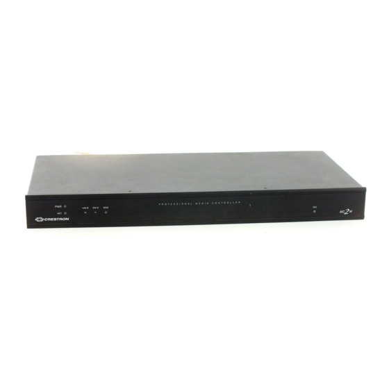
Page 8: Controls And Indicators
2-Series Professional Media Controller with RF Physical Views of the MC2W Controls and Indicators The MC2W front panel indicators and controls are described below. PWR (Power) This LED illuminates when the unit is connected to and receives 24 VDC power from an external power pack or the Cresnet NET connector. - Page 9 The CNXRMIRD that ships from Crestron requires some modification before use with the MC2W. THE CNXRMIRD ships with a mini phone jack that cannot be used with the 3-position connector on the IR IN port of the MC2W. To modify the CNXRMIRD to connect to the MC2W: Operations Guide - DOC.
- Page 10 6 (RXD+) in the cable. Refer to the table after this note, titled "COM Pinout to RS-485 Bus". 6 • 2-Series Professional Media Controller with RF: MC2W 3. Connect the bare wires of the CNXRMIRD to the appropriate pins on the 3-position connector supplied with the MC2W.
- Page 11 Data Carrier Detect Receive Data Transmit Data Data Terminal Ready Signal Ground Data Set Ready Request To Send Clear To Send Ring Ring Indicator 2-Series Professional Media Controller with RF: MC2W • 7 DESCRIPTION Male DB9 Connector Female DB9 Connector...
- Page 12 Other models, even from the same manufacturer, may not yield the same results. This connector is used for expansion to Cresnet peripherals. This connector can also serve as a 24V power source to Cresnet devices when the MC2W is powered by the 24 Y Z G external power pack, PW-2410RU.
-
Page 13: Memory
Crestron MC2W Memory The MC2W has 36MB of built-in memory (non-volatile and volatile). The total of 36MB is specified as follows: 4MB flash (non-volatile), 32MB SDRAM (volatile), and 256KB NVRAM (battery backed up). Flash memory contains the file system inside the 2-series control engine. Non-volatile memory contains information that is retained after the loss of electrical power. -
Page 14: Industry Compliance
NOTE: SDRAM is internal to operations and is not available to the programmer. Industry Compliance As of the date of manufacture, the MC2W has been tested and found to comply with specifications for CE marking and standards per EMC and Radiocommunications Compliance Labelling (N11785). -
Page 15: Setup
Particular attention should be given to supply connections other than direct connections to the branch circuit. (e.g., use of power strips). Two “ears” are provided with the MC2W so that the unit can be rack mounted. These ears must be installed prior to mounting. Complete the following procedure to attach the ears to the unit. -
Page 16: Bussing Strip Installation
To power additional devices from the MC2W’s NET connector, use the optional power pack PW-2420RU that can supply up to 38 Watts from the NET connector to Cresnet devices. -
Page 17: Hardware Hookup
Crestron MC2W Downloads | Product Manuals | Wiring Diagrams section of the Crestron website (www.crestron.com). NOTE: Do not power up system until all wiring is verified. Care should be taken to ensure data (Y, Z) and power (24, G) connections are not crossed. -
Page 18: Power Supply
2410RU, the MC2W can provide power to peripheral Cresnet devices (via the NET connector) up to a total of 14 Watts. The PW-2420RU allows the MC2W to provide up to 38 Watts to peripheral Cresnet devices (via the NET connector). -
Page 19: Establishing Communication With The Mc2W
+24VDC power to the peripheral devices by an alternate source. Establishing Communication with the MC2W Before uploading a program to the MC2W or performing diagnostic functions, the control system must be connected to a PC via the serial port in the rear of the unit. -
Page 20: Troubleshooting Communications
Consult the manufacturer’s documentation for further information about the COM ports on your PC. 3. Check the ERR LED indicator on the front panel of the MC2W. If this LED is illuminated, unplug the unit and reapply power after a few seconds. -
Page 21: Compiling And Uploading A Program To The Control System
Compiling and Uploading a Program to the Control System After you have completed your SIMPL Windows program using an MC2W, you must compile and upload the program to the control system. To compile the program, simply click the Convert/Compile button SIMPL Windows toolbar, or select Project | Convert/Compile (you can also press F12). -
Page 22: Uploading Touchpanel Projects
NOTE: Wireless touchpanels require Crestron cable number CNSP-586 to connect the wireless touchpanel to the MC2W via Cresnet. When connecting the touchpanel directly to the Cresnet connector on the rear of the MC2W, power to the MC2W must be supplied from the power pack (not the Cresnet connector). -
Page 23: Updating The Operating System
NOTE: Pages that are not present in the uploaded project are deleted. Updating the Operating System As with all 2-Series control systems, operating system files for the MC2W have a .cuz extension. You can obtain .cuz updates (when available) from the Downloads | Software Updates section of the Crestron website (www.crestron.com). -
Page 24: Advanced Console Commands
The SIMPL Windows online help file provides a full listing of console commands that are valid for 2-Series control systems. You can access the MC2W console via a serial connection (RS-232) with a PC. It is also possible to issue console commands through logic, by adding a Console symbol to the SIMPL Windows program. -
Page 25: Programming The Mc2W
03 to FE, designated as slave mode). In slave mode, the MC2W operates as a Cresnet device as part of a 2-series control system. For example, the MC2W can be part of a control system that includes IR, serial, Cresnet and RF devices, with touchpanels that operate the MC2W through the master 2-Series control system. -
Page 26: Programming With The Crestron Appbuilder
IR Database, and User Modules Directory. The Crestron AppBuilder accesses these tools behind the scenes, enabling you to easily create robust systems. NOTE: When using AppBuilder, the MC2W can only be programmed as a master device. Programming with SIMPL Windows... - Page 27 To add an IR device to the system, drag the device driver from the Crestron or User IR Database to a C2I-MC2-IR4 port. To add an RS-232 device, drag the C2IR one-way serial driver from the Serial Drivers folder to a C2I-MC2-IR4 port.
- Page 28 Program View. Then drag the symbol to Detail View. (Alternatively, double-click the symbol.) Slot 3: C2I-MC2-IO4 The MC2W provides four I/O ports called Versiports, each of which can function as a digital input, a digital output, or an analog input. Each Versiport has a corresponding pullup resistor.
- Page 29 Versiport 1 is at +5V. When <o1> goes high, Versiport 1 is shorted to ground. The <pu-disable1> signal is driven high. When <o1> goes low, Versiport 1 is floating. When <o1> goes high, Versiport 1 is shorted to ground. 2-Series Professional Media Controller with RF: MC2W • 25...
- Page 30 In Program Manager, drag the C2I-MC2-RY4 symbol from Program View to Detail View. 26 • 2-Series Professional Media Controller with RF: MC2W When Versiport 3 is shorted to ground, <i3> goes high. When Versiport 3 is not shorted to ground, <i3> goes low (so long as <pu-disable> equals 0 or is undefined).
- Page 31 When the signal goes low, the relay opens. If a signal is undefined, the relay is open. Slot 6: C2I-MC2-COM2 The MC2W provides two serial COM ports (A and B) that enable RS-232, RS-422, and RS-485 communication. Each port has a built-in serial driver with communication settings that must be specified in Configuration Manager: double-click a COM port to open the “Device...
- Page 32 In this example, we are using a PRO2 as the master. The PRO2 system view shows the MC2W as a slave device in slot 9 with a Net ID of 03 (assuming that no other C2NET devices are present as shown in the following illustration).
- Page 33 Setting the Net ID in Device Settings Double-click the MC2W icon to open the “Device Settings” window. This window displays the MC2W device information. If necessary, select the Net ID tab to change the Net ID, as shown in the following figure.
- Page 34 To do this you first open the program, and then replace the existing control system with the MC2W. That is, drag the MC2W from the Control Systems folder onto the existing control system in System Views, and click Yes when prompted to confirm the replacement.
- Page 35 SIMPL Windows online help file. Example Program An example program for the MC2W is available from the Crestron FTP site (ftp.crestron.com/Examples). Search for the file MC2W.zip that contains an example program, associated files, and a README.TXT file that describes the program where the MC2W operates in slave mode.
-
Page 36: Problem Solving
2-Series Professional Media Controller with RF Problem Solving Troubleshooting The following table provides corrective action for possible trouble situations. If further assistance is required, please contact a Crestron customer service representative. MC2W Troubleshooting (continued on next page) 32 • 2-Series Professional Media Controller with RF: MC2W... - Page 37 MC2W Troubleshooting (continued) System Monitor The System Monitor allows firmware to be reloaded into the MC2W in the event that firmware cannot be loaded in the normal mode. Perform the following procedure to correct the “System does not function” trouble situation on page 32 (in reference to Corrective Action).
- Page 38 ID of the device. NOTE: Slot locations vary from processor to processor. For example, on a PRO2, the COM slot location is number 4 while on the MC2W, the COM slot location is number 6. Specify the port (Port A or Port B) that the device is connected to, if applicable.
-
Page 39: Further Inquiries
Crestron award winning customer service team by calling: Firmware Upgrades To take advantage of all the MC2W features, it is important that the unit contains the latest firmware available. Therefore, please check the Crestron website (http://www.crestron.com/downloads/software_updates.asp) for the latest version of firmware. -
Page 40: Future Updates
Future Updates As Crestron improves functions, adds new features, and extends the capabilities of the MC2W, additional information may be made available as manual updates. These updates are solely electronic and serve as intermediary supplements prior to the release of a complete technical documentation revision. -
Page 41: Software License Agreement
This Agreement may only be modified by a writing signed by an authorized officer of Crestron. Updates may be licensed to You by Crestron with additional or different terms. This is the entire agreement between Crestron and You relating to the Software and it supersedes any prior representations, discussions, undertakings, communications or advertising relating to the Software. - Page 42 “applets” incorporated into the Software), the accompanying media and printed materials, and any copies of the Software are owned by Crestron or its suppliers. The Software is protected by copyright laws and international treaty provisions. Therefore, you must treat the Software like any other copyrighted material, subject to the provisions of this Agreement.
-
Page 43: Return And Warranty Policies
CRESTRON shall not be liable to honor the terms of this warranty if the product has been used in any application other than that for which it was intended, or if it has been subjected to misuse, accidental damage, modification, or improper installation procedures. - Page 44 Crestron Electronics, Inc. Operations Guide – DOC. 6143 15 Volvo Drive Rockleigh, NJ 07647 04.03 Tel: 888.CRESTRON Fax: 201.767.7576 Specifications subject to www.crestron.com change without notice.