Table of Contents
Advertisement
Advertisement
Table of Contents

Related Manuals for Crestron CP2


Summary of Contents for Crestron CP2
- Page 1 Crestron CP2 & CP2E 2-Series Compact Control System Operations Guide...
- Page 2 This document was prepared and written by the Technical Documentation department at: Crestron Electronics, Inc. 15 Volvo Drive Rockleigh, NJ 07647 1-888-CRESTRON All brand names, product names and trademarks are the property of their respective owners. ©2006 Crestron Electronics, Inc.
-
Page 3: Table Of Contents
Crestron CP2 & CP2E Contents 2-Series Compact Control System: CP2 & CP2E Introduction ... 1 Features and Functions ... 1 Specifications ... 3 Physical Description... 4 Industry Compliance ... 8 Setup ... 9 Network Wiring... 9 Identity Code ... 9 Hardware Hookup ... -
Page 5: 2-Series Compact Control System: Cp2 & Cp2E
1. For more information on internal memory, refer to “2-Series Memory & Directory Structure” in the 2. CP2E only. 2-Series Engine At the heart of the CP2 & CP2E is the powerful 32-bit Freescale ColdFire processor. Crestron's exclusive enhanced real-time operating system makes the CP2 & CP2E the fastest, most reliable control systems available. - Page 6 2-Series Compact Control System Cresnet Slave Mode Selectable Cresnet Slave Mode enables the CP2 & CP2E to be configured as Cresnet slave devices, effectively transforming them into Cresnet expansion modules. Such flexibility can offer a cost-effective solution for system expansion, providing a host of additional control ports in a single module.
-
Page 7: Specifications
Crestron CP2 & CP2E Specifications Specifications for the CP2 & CP2E are listed in the following table. CP2 & CP2E Specifications Operations Guide – DOC. 5980A 2-Series Compact Control System SPECIFICATION Processor Processing Speed Memory SDRAM NVRAM Flash Operating System... -
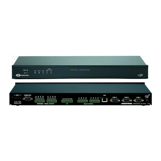
Page 8: Physical Description
This section provides information on the connections, controls and indicators available on your CP2 & CP2E. CP2 Physical Views CP2E Physical Views 4 • 2-Series Compact Control System: CP2 & CP2E Crestron CP2 & CP2E Operations Guide – DOC. 5980A... - Page 9 Crestron Toolbox™. LNK – Indicates when there is a connection to the rear panel LAN port. ACT – Indicates communication (activity) at the rear panel LAN port. 2-Series Compact Control System: CP2 & CP2E • 5 6.64 in (16.86 cm) DESCRIPTION 1.70 in...
- Page 10 RELAY OUTPUT (Continued on following page) 6 • 2-Series Compact Control System: CP2 & CP2E HW-R - Initiates system hardware reset. SR-R - Pressing this in combination with HW-R button performs a system restart without loading the program. Pressing it alone while the system is running restarts the program.
- Page 11 4. The orientation of this connector is “upside down” compared to other Crestron network devices (e.g. CNX-BIPAD8, CNX-RMCLV). To avoid damage to the CP2 or CP2E unit, be sure the mating Cresnet cable connector is properly aligned before attempting to insert it.
-
Page 12: Industry Compliance
2-Series Compact Control System Industry Compliance As of the date of manufacture, the CP2 & CP2E have been tested and found to comply with specifications for CE marking and standards per EMC and Radiocommunications Compliance Labelling. NOTE: This device complies with part 15 of the FCC rules. Operation is subject to... -
Page 13: Setup
Identity Code Net ID The Net IDs of the CP2 & CP2E have been factory set to 02. This Net ID is defined as the “Master” control system. The Net IDs of multiple CP2 & CP2E devices in the same system must be unique; this means there will be a master/slave relationship between units (only the Net ID of the master will be left at 02). - Page 14 2-Series Compact Control System Rack Mounting The CP2 & CP2E can be mounted in a rack or stacked with other equipment. Two “ears” are provided with the CP2 & CP2E so that the unit can be rack mounted. These ears must be installed prior to mounting. Complete the following procedure to attach the ears to the unit.
- Page 15 * The units can be powered through the NET network connector or by an optional AC power pack (purchased separately). If an external power supply is to be used, Crestron recommends its CNPWS-75 External Power Supply or PW-2420RU Universal Power Pack or equivalent.
-
Page 16: Programming Software
SystemBuilder from the Crestron website and examine the extensive help file. Programming with SIMPL Windows NOTE: While SIMPL Windows can be used to program the CP2 & CP2E, it is recommended to use SystemBuilder for configuring a system. SIMPL Windows is Crestron’s premier software for programming Crestron control systems. -
Page 17: Example Program
Detail View. A description for each signal in the symbol is described in the SIMPL Windows help file (F1). Example Program An example program for the CP2 & CP2E is available from the Crestron website (http://www.crestron.com/exampleprograms). Operations Guide – DOC. 5980A 2-Series Compact Control System •... -
Page 18: Uploading And Upgrading
Use Crestron Toolbox for communicating with the CP2 & CP2E; refer to the Crestron Toolbox help file for details. With the CP2, this connection to the computer must be a direct serial connection; with the CP2E the connection can be either serial or TCP/IP. -
Page 19: Programs And Firmware
Alternatively, use a CAT5 crossover cable to connect the two LAN ports directly, without using a hub or router. • Use the Address Book in the Crestron Toolbox to create an entry for the CP2E with the CP2E’s TCP/IP communication parameters. •... -
Page 20: Operation
The CP2 and CP2E both require 24 watts of power to operate. Therefore, if you use a PW-2420RU power supply (rated at 50 watts), you will have 26 watts of power left over to run additional Cresnet devices. -
Page 21: Problem Solving
Crestron CP2 & CP2E Problem Solving Troubleshooting The following table provides corrective action for possible trouble situations. If further assistance is required, please contact a Crestron customer service representative. CP2 & CP2E Troubleshooting (Continued on following page) Operations Guide – DOC. 5980A... -
Page 22: Check Network Wiring
“Network Analyzer”. Battery Replacement A Lithium battery is used to power the system clock within the CP2 & CP2E. Under normal conditions, it will last for approximately 10 years. In the event that the clock fails, only an authorized technician should replace it. -
Page 23: Reference Documents
Cresnet power usage of the entire chain. If the unit is a home-run from a Crestron system power supply network port, the Cresnet power usage of that unit is the Cresnet power usage of the entire run. -
Page 24: Future Updates
For assistance in your local time zone, refer to the Crestron website (http://www.crestron.com/) for a listing of Crestron worldwide offices. You can also log onto the online help section of the Crestron website to ask questions about Crestron products. First-time users will need to establish a user account to fully benefit from all available features. -
Page 25: Software License Agreement
This Agreement may only be modified by a writing signed by an authorized officer of Crestron. Updates may be licensed to You by Crestron with additional or different terms. This is the entire agreement between Crestron and You relating to the Software and it supersedes any prior representations, discussions, undertakings, communications or advertising relating to the Software. - Page 26 “applets” incorporated into the Software), the accompanying media and printed materials, and any copies of the Software are owned by Crestron or its suppliers. The Software is protected by copyright laws and international treaty provisions. Therefore, you must treat the Software like any other copyrighted material, subject to the provisions of this Agreement.
-
Page 27: Return And Warranty Policies
Purchasers should inquire of the dealer regarding the nature and extent of the dealer's warranty, if any. CRESTRON shall not be liable to honor the terms of this warranty if the product has been used in any application other than that for which it was intended, or if it has been subjected to misuse, accidental damage, modification, or improper installation procedures. - Page 28 Crestron Electronics, Inc. Operations Guide – DOC. 5980A 15 Volvo Drive Rockleigh, NJ 07647 (2002062) Tel: 888.CRESTRON 06.06 Fax: 201.767.7576 Specifications subject to www.crestron.com change without notice.