Table of Contents
Advertisement
Advertisement
Table of Contents

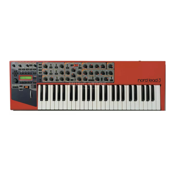
Summary of Contents for Clavia nord lead 3
- Page 1 SERVICE MANUAL...
-
Page 2: Table Of Contents
Error Codes ................6 Hardware ..................7 Hardware structure ..............7 Opening the synth............... 8 Hardware configuration............... 9 Calibrating the DACs ..............9 Software ..................10 Spare Parts................. 11 Clavia DMI Service manual Nord Lead 3 rev. 1.1 Page 1... - Page 3 The Nord Lead 3 Service manual is arranged to help our service centers in the best way possible. However the Nord Lead 3 user manual is a very useful guide, use it as a reference in addition to this service manual. If you have access to internet you’ll find the user manual available for download and also a lot of useful information on our website www.clavia.se...
-
Page 4: Overview
Rack 3 W: 870 mm W: 19” D: 278 mm D: 100 mm (incl feet and knobs) H: 100 mm H: 5 rack units Weight: 6,3Kg Weight: 3,3 Kg Clavia DMI Service manual Nord Lead 3 rev. 1.1 Page 3... -
Page 5: Test Program
- Press [ Navigator Left ] or [ Navigator Right ] to toggle within a test. - Press [ Active Device ] to start or reset a test. A text guiding through the different tests should appear on the LCDs. Clavia DMI Service manual Nord Lead 3 rev. 1.1 Page 4... - Page 6 4. Encoder 2: Turn the encoders as indicated. << indicates turning an encoder fully counter clockwise, >> indicates turning an encoder fully clockwise. Turning an encoder too quickly requires restarting the test. Clavia DMI Service manual Nord Lead 3 rev. 1.1 Page 5...
-
Page 7: Error Codes
E.6 No OS detected (no OS in Flash) E.7 OS load error (OS with errors in Flash) E.8 Flash init error (can't init Flash chip(s)) E.9 Flash unknown (unknown Flash chip(s)) Clavia DMI Service manual Nord Lead 3 rev. 1.1 Page 6... -
Page 8: Hardware
They also differ in size. Power supply The Nord Lead 3 is supplied with several different voltages from the power board. These are +3.3V, ±5V and ±12V. For more information on where to measure these voltages see the appropriate schematic. -
Page 9: Opening The Synth
Loosen the screws Lead / Rack (40262 holding the LCD board to the upper lid. You can now lift out the LCD board. Clavia DMI Service manual Nord Lead 3 rev. 1.1 Page 8... -
Page 10: Hardware Configuration
Always use the latest OS version! Calibrating the DACs The Nord Lead 3 is equipped with two stereo D/A converters U39 and U42 running at 18 bits 44,1 kHz. The DACs are calibrated with external trim potentiometers (trimmers) at the factory for lowest possible distortion. -
Page 11: Software
To make sure you don’t accidentally overwrite Sounds or performances you want to keep, it’s a good idea to back up the sounds. For information on how to back up programs and Performances, please refer to the Nord Lead 3 User Manual Factory presets... -
Page 12: Spare Parts
40025 Screw, modulation wheel 40026 Screw, pitch stick/upper lid 40018 Screw, upper/lower lid 40110 Upper lid Nord Lead 3 40112 Upper lid Nord Rack 3 40046 Washer BRB 4,3*9*0,8 Clavia DMI Service manual Nord Lead 3 rev. 1.1 Page 11... - Page 13 22040 Button red Nord 22610 Connector 1/4" Stereo/switch 22670 Connector 16 pole, micromatch 22520 Connector 26 pole 22500 Connector 20 pole 22480 Connector 10pol 22550 Connector 4 pole, after touch 90 deg. Clavia DMI Service manual Nord Lead 3 rev. 1.1 Page 12...
- Page 14 40042 Screw, regulator powerboard 40056 Nut M3 21660 Regulator -5Low 21680 Regulator +12V 21700 Regulator -12V 21690 Regulator -5V 40176 Plastic isolator 40180 Spacer 2mm Nylon 22790 Trafo N3 Jpn Clavia DMI Service manual Nord Lead 3 rev. 1.1 Page 13...


