Advertisement
Quick Links
ASSEMBLY INSTRUCTIONS
INSTRUCCIONES DE ARMADO
ATTENTION
DO NOT RETURN
TO THE STORE
Contact
MD Sports
Customer Service
* For additional resources and Frequently
Asked Questions, please visit us at
themdsports.com
TM
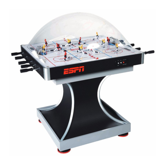
MODEL/MODELO: AWH042_017E
ATENCIÓN
NO DEVOLVERLO
A LA TIENDA
Contacto
MD Sports
Servicio al Cliente
* Por mayor información y Preguntas
Frecuentes, favor visitarnos en
themdsports.com
SAM'S US
Advertisement

Related Manuals for MD SPORTS AWH042 017E


Summary of Contents for MD SPORTS AWH042 017E
- Page 1 DO NOT RETURN NO DEVOLVERLO TO THE STORE A LA TIENDA Contact Contacto MD Sports MD Sports Customer Service Servicio al Cliente * For additional resources and Frequently * Por mayor información y Preguntas Asked Questions, please visit us at Frecuentes, favor visitarnos en themdsports.com...
- Page 2 English Español LIMITED 90 DAYS WARRANTY GARANTÍA LIMITA DE 90 DIAS This product is covered by a limited warranty that is effective for Este producto está cubierto por una garantía efectiva de 90 días a 90 days from the date of purchase. If, during the limited partir de la fecha de su compra.
-
Page 3: Assembly Tips
English Español TOOLS REQUIRED HERRAMIENTAS NECESARIAS Destornillador Phillips - No incluido Phillips Screwdriver - Not Included Power Tools Herramientas eléctricas - Set Low Torque - Bajo par Destornillador de Cabeza Plana - No incluido Standard (Flat Head Screwdriver) - Not Included Llave Inglesa - Incluido Wrench - Included... - Page 4 Español English AWH042_017E PARTS LIST / LISTA DE PARTES FOR FIG. 6 FOR FIG. 2 FOR FIG. 2 FOR FIG. 2 Nivelador de Bottom Pedestal Pedestal de fondo Top Pedestal Pedestal superior Mainframe Unidad Principal Leg Leveler Pierna FOR FIG. 1 FOR FIG.
- Page 5 Español English AWH042_017E PARTS LIST / LISTA DE PARTES FOR FIG. 1, 8 FOR FIG. 1, 2, 7, 9 FOR FIG. 1, 8 FOR FIG. 6 Tirador 3/16" Nut Tuerca 3/16" Allen Key Llave Allen Wrench Llave Inglesa Handle FOR FIG. 9 FOR FIG.
- Page 6 Español English FIG. 1 X 16 X 16 Note: Place the Barrel Nuts (#31) into the Legs (#5). / Nota: Coloque las Tuercas de barril (#31) en las Piernas (#5). FIG. 2 FIG. 2B X 16 X 16 Note: Turn over the FIG. 2A FIG.
- Page 7 Español English X 28 FIG. 3 FIG. 2B Assembly / Montaje FIG. 2B Note: Attach the Leg Panels (#30) to the FIG. 2B Assembly using seven Screws (#21) per Leg Panel. / Nota: Ate los paneles de pata (#30) a la unidad FIG.
- Page 8 Español English FIG. 5 FIG. 5A Note: Insert the Trim Strips - A (#28) into the Trim Strips - B (#29). / Nota: Inserte las tiras de recorte - A (#28) en las tiras de recorte - B (#29). FIG. 6 Remove the Playfield (#8) from the Mainframe (#1).
- Page 9 Español English FIG. 7 FIG. 5 Assembly / Montaje FIG. 5 FIG. 8 X 12 AWH042_017E www.themdsports.com (Continued on the next page.) (Continúe en la siguiente página.)
- Page 10 Español English FIG. 9 FIG. 9C FIG. 8 Assembly / Montaje FIG. 8 Connect the Scorer Display Wires (#P1 & #P2) and the Adapter (#38). FIG. 9A P1 & P2 / Conecte los Cables de Exposición de Marcador (#P1 & #P2) y el adaptador (#38).
- Page 11 Español English ORDER OF PLAYERS FIG. 10 (Overhead View) / Orden de Jugadores (Vista en General) FIG. 10A Yellow / Amarrillo Note: Insert each Goalie (#14 and #18) Red / Rojo and each Player (#13, #15, #17, #19) into each gear box in the order shown.
- Page 12 Español English FIG. 11 Electronic Connections Diagram / Diagrama de Conexión Electrónica Scorer Display Scorer Display / Exposición de Marcador FIG. 12 / Exposición de Marcador Scorer Display Wire - Short / Cable de Exposición de Marcador - Corto Adapter / Adaptador Scorer Display Wire - Long / Cable de Exposición...
- Page 13 Español English ELECTRONIC SCORER OPERATION OPERACION DEL MARCADOR ELECTRONICO 1. Plug in the power cord and switch power to "ON". 1. Enchufe el cable de potencia y el interruptor de potencia a “ON”. 2. Press the "MINUTES" button to set up playing time. 2.