Summary of Contents for Toshiba 1400 XL PLUS Series
- Page 1 TOSHIBA Battery Cabinet System SINGLE PHASE - 2.4/3.6/6.0/8.0 KVA PLUS MANUFACTURED IN THE U.S.A. OPERATION MANUAL October, 1996 Part # 43241-002...
- Page 2 TOSHIBA...
- Page 3 This manual may change without notice. Contact your local Toshiba sales office to verify that this is the latest revision. Should further information be desired or should particular problems arise which are not covered sufficiently for the purchaser's purposes, the matter should be referred to the local Toshiba sales office.
-
Page 4: General Safety Instructions
TOSHIBA GENERAL SAFETY INSTRUCTIONS Warnings in this manual appear in any of four ways: Danger- The danger symbol is a lightning bolt mark enclosed in a triangle which precedes the 3/16" high letters spelling the word "DANGER". The danger symbol is used to indicate imminently hazardous situations, locations, and conditions which, if not avoided, WILL result in death, serious injury, and/or severe property damage. -
Page 5: Table Of Contents
TOSHIBA CONTENTS SECTION PAGE Disclaimer ......................i General Safety Instructions ................. ii Contents ....................... iii Important Safety Instructions ................1-1 Inspection/Storage/Disposal ................2-1 Inspection of the new Battery System ............2-1 Storage of the Battery System ..............2-1 Disposal ....................2-1 Precautions ...................... -
Page 6: Important Safety Instructions
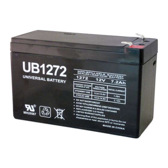
216VDC 8.0 KVA: 252VDC Servicing of the batteries should only be performed by a qualified Toshiba Representative who is knowledgeable of batteries and the required precautions. Keep unauthorized personnel away from batteries. When replacing batteries, use the same number and type of one of the following sealed, lead-acid... - Page 7 TOSHIBA IMPORTANT SAFETY INSTRUCTIONS WARNING Proper maintenance to the battery system of this unit must be done by a qualified service techincian, this is essential to the safety and reliability of your UPS system. Refer to service manual. DANGER A battery can present a risk of electrical shock and high short circuit current.
-
Page 8: Inspection/Storage/Disposal
It is illegal to dump lead-acid batteries in landfills or dispose of improperly. Please help our Earth by contacting the environmental protection agencies in your area, the battery manufacturer, or call Toshiba toll-free at 1-800-231-1412 for more information about recycling. -
Page 9: Precautions
This will result in damage to the UPS, the Battery System, or both. Call your Toshiba representative if you should have any ques- tions. Before connecting the Battery System to the UPS; move the (MCCB-C) switch OFF position. -
Page 10: Ups Connections
TOSHIBA Power Connections Power Connections The following illustration details the wiring connections from the power distribution panel (not part of the UPS) to the UPS unit and the Battery unit. This connection diagram is to be used with the following Battery units: UC3-BC-0230, 0260, 0330, 0360, 0630, 0660, and 0830. -
Page 11: 8.0Kva Connection
TOSHIBA Connection Instructions and Diagrams Battery Connections The following illustrations detail the wiring connections between the UPS unit and the Battery Unit. DANGER Contacts are not rated with interrupting capacity. DO NOT attempt to connect the UPS to the Battery Cabinet without having the MCCB switch on the rear panel of the UPS and Battery Unit, in the OFF position. -
Page 12: Battery Connections
TOSHIBA Connection Instructions (continued) Battery Connections DO NOT attempt to connect the UPS to the Battery Unit without having the MCCB switch (ON/OFF), on the rear panel of the UPS and Battery Unit, to the OFF position. DANGER NOTE: Use only compatible cabinets! UPS typeform "UC3G2L024C6(#)"... -
Page 13: Preventative Maintenance/Parts Replacement
Preventive and Scheduled Maintenance/Parts Replacement Preventive Maintenance Toshiba's 1400XL Plus Series of UPS battery cabinets have been designed to provide years of trouble-free operation requiring a minimum of preventive maintenance. The best preventive measure that the battery cabinet user can take is to keep the area around the unit, particularly the air inlet vents, clean and free of moisture and dust accumulations. -
Page 14: External Layouts
TOSHIBA External Layouts/Dimensions/Shipping Weights External Layouts Front View Side View Dimensions Dimensions Model UC3-BC-0230 22.2 in. 10 in. 27.2 in. 19.4 in. 2.2 in. 2.76 in. UC3-BC-0260 (555 mm) (250 mm) (680 mm) (486 mm) (55 mm) (69 mm) UC3-BC-0330 22.2 in. -
Page 15: Epo Connection
TOSHIBA Emergency Power Off (EPO) Connections Shunt Trip A shunt trip for the DC breaker on the battery cabinet is provided. This device is operated with an applied voltage of 120VAC. When voltage is applied, the shunt trip will cause the breaker to switch to the OFF position disabling the battery cabinet. - Page 16 TOSHIBA...
- Page 17 TOSHIBA...
- Page 18 TOSHIBA TOSHIBA INTERNATIONAL CORPORATION INDUSTRIAL DIVISION 13131 West Little York Rd., Houston Texas 77041 Tel: [713] 466-0277 Fax: [713] 466-8773 Telex: 762078 Printed in U.S.A.


