Table of Contents
Advertisement
Quick Links
Advertisement
Table of Contents

Related Manuals for Honeywell NOTIFIER AM-8000


Summary of Contents for Honeywell NOTIFIER AM-8000
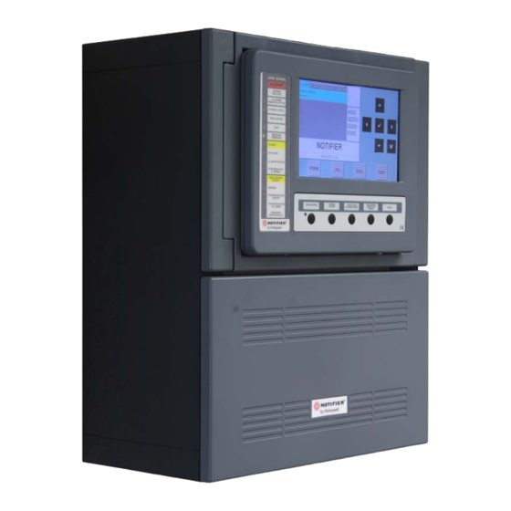
- Page 1 AM-8000 Programming Manual Intelligent Addressable Fire detection...
- Page 2 AM-8000 Programming Manual INDEX AM8000_ind Doc. M-160.2-AM8000-ENG Rev. A.1 NOTIFIER ITALIA...
-
Page 3: Table Of Contents
INDEX Definitions Front panel Comands Front Panel LEDs User Interface Keyboard and Function keys Normal Condition Alarm Condition Fault Condition (Zone) Fault Condition (System) Test Condition (zone alarm in walk-test) List of Disabled elements PROGRAMMING Menu System Line Timings Password Panel Name Points Programming Detectors... - Page 4 Display / Modify Status Detectors Status Modules Status Groups Status Zone Status Display Active Modules FIRMWARE version Disabile Menu Detectors Modules Zone System TEST menu Zone APPENDIX –CONTROL BY EVENT Equations Operators Examples AM-8000 Programming Manual INDEX AM8000_ind Doc. M-160.2-AM8000-ENG Rev. A.1 NOTIFIER ITALIA...
-
Page 5: Definitions
Do not try to use the control unit and devices connected without reading this manual DETECTION SYSTEM LIMITS An alarm or fire detection system can be very useful for the prompt warning of any dangerous event such as fire. In some cases it can automatically manage events (transmission of messages for room evacuation, automatic fire-extinguishing, TVCC system interface, access route or door blockage, automatic warning to authorities, etc.), but in any case, it does not ensure protection against damages to propriety). - Page 6 EVACUATION: You must know the level 2 password to perform this operation.. Control for the activation of the Siren output and of all output modules programmed with SW-TYPE ID = HORN in absence of Alarms and Faults. If you press this button once more all the previously activated outputs will be deactivated. END DELAY: This button is active only in case of alarm if the immediate activation of the siren outputs in the exclusions menu has been excluded.
-
Page 7: System
LIGHT SIGNALLINGS OF THE FRONT PANEL ALARM (Red): It flashes if there is at least one device in alarm and it has not been recognized yet. It is permanently lit if all alarm events have been recognized. ACTIVE REMOTE ALARM (Red): it is permanently lit if the output towards the fire alarm transmission devices (telephone dial) has been activated. -
Page 8: User Interface
Functions and Access level Functions EN.54 Level Factory default password Alarm and Faults display Level 1 none Alarm and Faults recognition Level 1 none Delay Re-set (appropriate button) Level 1 none Excluded Zones/Points display Level 1 none Exclusions menu Level 2 22222 Test Menu... -
Page 9: Normal Condition
Normal condition Icons which signals the Panel Conditions. - The NOTIFIER brand symbol appears in the absence of alarms and Faults. - If there are Alarms the Fire symbol is displayed - If there are Faults the Triangle symbol is displayed. N.B. - Page 10 By pressing the enter key you can access the list of point in alarm of the zone selected on the display, through the arrow keys you can scroll the list of the devices in alarm. Device in Alarm D = Detector M = module Text programmed For this Device...
-
Page 11: Fault Condition (Zone)
Detail of the Device in Fault Condition Text programmed Counter for the device of Faulty zones Fault Type description Through further pressures of the enter key the display of the point name alternates with one of the Faultdetail, refer to the following figure: Condition with System fault events (control unit faults) ... - Page 12 Condition with alarm events from a zone under Test Alarm event from zone under test Date and Time of the Event Through a first pressure of the enter key you can display the list of devices with the indication of the point name;...
-
Page 13: Programming Menu
RECOMMENDED SEQUENCE TO PERFORM THE CONTROL UNIT PROGRAMMING The following operation sequence is recommended to perform the initial programming of the control unit, to prevent mistakes and consequent loss of time. The details of each operation are pointed out in the following pages. - Perform the wiring of the control unit lines and perform the appropriate tests as described in the installation manual before powering the control unit. - Page 14 Programming menu By pressing the “PGRM” function key you can access the programming menu, to perform the configuration of the system or make changes to the programming. To access the Programming menu you must enter the Level 3A password (44444 is the default password) To enter the password use the keyboard that appears on the screen.
-
Page 15: Line
Programming – System - LINE Style: OPEN LINE, CLOSED LOOP This function allows to change (in memory) the type of line connection, according to the NFPA coding ( Open = style 4, LOOP = style 6 ) and the scan priority of the devices connected to it. Press one of these key to select the Previous or Next line Through a first pressure of the enter key the Line editing function is activated,... - Page 16 DETECTORS folder Press the right Arrow key 4 to change the time of check for the detectors: Detectors verification time allows the control unit to perform a check for all installed sensors, for the set time, before confirming the possible alarm. Detectors Verification Time is programmable in seconds ( Max.
-
Page 17: Password
FAULTS signalings timings folder Press the right Arrow key4 to change the parameters to manage the Fault signallings: : MAINS FAULT DETECTION TIME is the minimum time during which Mains Fault is signalled if there is no mains TX FAULT DELAY TIME (function not implemented) Mains Loss Timings are expressed in... - Page 18 This function allows to enter a programmable text for the Panel. This text can have a maximum of 32 characters and is displayed on the screen in the absence of alarms and faults (Normal Condition) To enter the system name press the enter key and use the alphanumerical keyboard to enter the text.
-
Page 19: Detectors
Programming - Points From the Programming menu by selecting the “Points” item is displayed the following screen, where you can manually configure each type of addressable device on field ( Detectors or Modules ). Detectors By selecting “DETECTORS” and by confirming the selection through the enter key you enter the programming procedure for Addressable Sensors. - Page 20 Valid Types for ADVANCED Protocol Detectors HW Type SW Type description PHOT NFXI-OPT TFIX58 THER58 NFXI-TFIX58 TFIX78 THER78 NFXI-TFIX78 TDIFF THERDIFF NFXI-TDIFF SMT2 OMNI NFXI-SMT2 SMT3 OMNIIR NFXI-SMT3 SMART4 OMNICIR IRX-751CTEM-W SMART4 Valid Types for CLIP Protocol Detectors HW Type VISUAL MESSAGE TYPE OF DEVICE PHOT...
- Page 21 CBE for this point: If a CBE is already programmed it’s displayed here, other ways the field is empty as show. Use the alphanumerical keyboard to enter the data at the end, press the ENTER key on the keyboard screen to confirm. Program Zone associated to Detector Points are assigned to a Zone for a proper display of the alarm location.
- Page 22 Tracking By enabling the tracking option when the device exceeds the alarm threshold the control unit activates the following indications. - Output modules associated through CBE - Buzzer - Control unit siren output - Alarm point indication on the display When the point returns in normal state the output modules associated through CBE return idle, while the following signaling are still active: - Buzzer...
- Page 23 Perform the “Paste From …to” control for the programming of block points as indicated: Paste From ..to enter the start address through the arrow keys or by using the FROM : xx keyboard press the enter key confirm the datum enter the ending address through the arrow keys ...
-
Page 24: Zone
Example of programming of a CLIP sensor with Type-Id “PINN” PINNACLE 7251 First folder or main folder (Progr. of Type ID and reading associated with the sensor) PROGRAMMINGS MENU \Points\Detector Protocol used for this device MAIN. PROGRAM OPTION EDIT Protocol CLIP SW Type_ID SW Type... -
Page 25: Modules
MODULES By selecting the “Modules” item and confirming the selection through the enter key you enter the programming procedure. This procedure is made up of 4 programming folders (to access the folders use the arrow keys 4) The display shows by default the first device of the first line. Use the function keys to select another device. - Page 26 For a description of “How-to” operate and the description of Tracking and Led-Blink field, please refer to Sensor programming screen before detailed. The folders for the output modules are described as follows: Led on device enabled to blink Enable manual silence Enable self - silence Pag.
-
Page 27: Auto-Learn
Auto-learn ( automatic recognizion of devices installed ) From the Points menu, by selecting the “Auto-Learn” item and confirming the selection through the enter key you enter the self-programming procedure of the devices installed on the line. Verify Double Address: YES By selecting YES, panel will check for more than one device programmed with same address in a line. - Page 28 Where: TYPE = Type of devices found ( see table above) ew device found NEW = N NFO = Devices previously programmed but not coherent with what was detected during the Auto-Learn procedure = total of devices detected on the line ( NEW + INC + correctly programmed devices.) MAN = Devices previously programmed but not detected during the Auto-Learn The CONF control saves the devices detected during the Self-Learn according to the following mode: - NEW and INC are initialised through the default data.
- Page 29 Summary of HW Type-ID for Modules ( displayed after an Auto-Program ) ADV protocol devices HW Type Description 1OUT M701 ( 1 output module ) OUT-240 M701-240-DIN ( 1 output module 230 vac) M700KI ( Manual Call Point ) MCPW M700KW ( Outdoor Manual Call point ) M710 ( 1 input module )
-
Page 30: Inputs Modules
Summary of SW Type-ID for modules INPUT MODULES CONNECTION TYPE TYPE OF DEVICE ABBREVIATION MON3 Input module Input module used for N.O. contacts (Connection in conformity with EN54 rule). Input module Input module used for N.O. contacts or any device SCON MMX-2 input module Input module used for 4- wire conventional smoke detectors... -
Page 31: Outputs Modules
OUTPUT MODULES ABBREVIATION TYPE OF DEVICE Output module with supervision of the device connection line FORC Output module with relay contacts free from voltage OUTPUT MODULES FOR GENERAL SIGNALLINGS ABBREVIATION TYPE OF DEVICE PWRC FORC Output module used to temporarily interrupt power supply, during SYSTEM RESET, for the 4- wire conventional smoke sensors, powered by a remote power supply. - Page 32 For UDS panels two specific Type ID are reserved, UDS1 and UDS2. UDS units can be installed from the tenth starting address with the exclusion of the decade from 0 to 9, and occupy from a minimum of 2 to a maximum of 6 addresses. The basic installation, compatible with UDS-1N type units ( now obsolete ) , occupies the first two addresses to which the type-ID UDS1 is assigned;...
-
Page 33: Groups
Programming Groups menu A group is a set of software devices that can perform associations. When a sensor or a module (which belong to the group) are in alarm, the group activates. If an output module is a member of the same group, it will be activated. This procedure is composed of 3 programming folders where to enter data is applied the editing function previously described in the paragraph: description of the keyboard operation to enter data paragraph The AM-8000 control unit has 400 groups, which can be programmed as:... - Page 34 CBE equation To change the “CBE” field in this folder, select the parameter through the arrow keys (the characters of the selected field are in Reverse), press the enter key and use the alphanumerical keyboard to enter the data; at the end press the enter key to confirm CROSS ALARM...
- Page 35 G301 = TIM ( 18.00 08.30) Example: CBE of the high sensitivity group G302 = TIM ( 08.30 18.00) CBE of the low sensitivity group For the Detector to which this function is to be coupled the parameter “Daytime/Night = YES ”(refer to Detectors programming) must be programmed.
- Page 36 Programming - AM-8000 menu This function enable the AM-8000 multi-box configuration. One “master” and up to 7 additional CPU can be configured in a Network using the Hi speed Can-Bus ports. The “Master” panel must always be set to Address #1 ( dip-switch SW1 on CPU card ) ...
-
Page 37: Utility
Programming - AM-8000 menu This function will restore all Default programming ( NO NETWORK ): By selecting UTIL from the display of the system state screen you can access the Utility menu, which includes some functions generally used by servicing personnel To access the menu, enter the Level 3 Password (33333 is the default password). -
Page 38: Date And Time
UTILITY Date and Time This function allows to program the time and date of the control unit. To change values in “Date and Time” programming Form use the arrows 4 to select the field to be changed (the characters of the selected field are white on dark background). -
Page 39: Special Parameters
Parameters By selecting the “Parameters” item, you can perform the configuration of the local and special parameters according to the following figure By selecting “NO” in the “Led Blink” function the led flashing is disabled for all the points installed during the line interrogation. - Page 40 DRIFT WARNING FUNCTION - By enabling this function, the control unit generates a signalling when the sensor exceeds 70% of the alarm threshold for more than 5 minutes. This signalling can be used as a warning to perform a cleaning of the sensor optical chamber. This function is a general enable parameter valid for all the control unit points.
-
Page 41: History Log
The historical file has a maximum capacity of 2000 events. When 1990 stored events are reached, the control unit in correspondence of a new event cancels the least recent event and stores the new event. DISPLAY This function allows the display of the events in the Historical File. - Page 42 selecting “Display” the first 3 event are diplayed Use the arrows keys to scroll the list of all events. History Log CLEAR: By selecting the “Clear” function the following display appears: Press the enter key to perform the cancellation of all events stored in the historical event.
- Page 43 History – Log Save: This function will save the History Log file in an USB-MEMORY STICK . Not yet implemented in this Firmware version This function allows to examine the state of a point and in case of a detector, the analogue value can be displayed.
- Page 44 The display shows by default the first device of the first line. To select another device use the function keys Module Status depends on Module Type ( Input or Output ) Modify the Output Status of a Control Module After selecting the “On/Off” field using the arrow keys ...
- Page 45 The display shows by default the first Zone. To select another Zone use the function keys – – Through this function you can examine the active module lists which are connected to the control unit lines. Display of Input Modules : Active AM_8000 Programming Manual PAGINA - 41...
- Page 46 In case of no alarm input modules in a line, there will be the following indication shown: “ No Input Module Active” Display of Output Modules : Active In case of no active output modules in a line there will be the following indication shown in the figure below: “...
- Page 47 By pressing the DISABL function key in System State screen you can access the Disable menu, where detectors, modules, zones, etc. can be disabled The following menu is displayed By selecting the “Display” item the user enter the following menu where devices are displayed by the type: Counters of n°...
- Page 48 Modify Status - Detectors The display shows by default the first device of the first line. To select another device use the function keys. When a detector is Disabled the control unit is inhibited to the reception of the Alarm and Faults signaling from the sensor.
- Page 49 System Exclusion This procedure is composed of 4 programming folders where the editing function previously explained is applied to enter data. This function allows the Sounder output Disablement (CNU-33 and CNU-34 terminals on the basic board) and all output modules programmed through Type_ID “HORN”.
- Page 50 This function allows the exclusion of all the output modules programmed through TYPE ID “UDS1” ( UDS and UDS2-N extinguishing panels) and select through the arrow keys “YES” To change this parameter in this folder press the enter key or “NO”...
- Page 51 Zone TEST : This function allows to start the Walk-Test procedure for a selected zone. This procedure is composed of 2 folders where the editing function previously explained is applied to enter data. Enter the zone number for which the test function must be activated.
-
Page 52: Operators
– – A typical programming of the control unit is defined as CONTROL-BY-EVENT EQUATION (CBE). During the programming phase, a CBE equation must be associated with each point, zone or group The CONTROL-BY-EVENT equation allows to program a series of conditions that the control unit will assess when the Point, the Zone, the Group are ACTIVE, and will perform the programmed operations. - Page 53 CBE “Null”:equation You can also not program any equation for a device. In this case: - If the device in question is an input sensor or module, the control unit will activate only all general visual and sound indications (Alarm LED on the front panel, General Alarm RELAY, BUZZER and possible output modules programmed through TYPE ID software for general signallings).
- Page 54 N.B. It is not allowed to write a CBE for a direct group, if the operands contained inside the round brackets are some groups having an index lower than the group for which the CBE must be associated as in the following example: CBE not allowed G33 = (G23 G24)
- Page 55 is the operator which allows to program some activation delays for specific conditions. The device which has in its CBE equation the “DEL” operator, when its equation is true, waits for the programmed time before activating. If during this delay time its equation is not true any longer, the timer resets and is ready to start at the next event (therefore the output device does not activate) FORMAT : OF (MM.SS (delay) MM.SS.
- Page 56 SDEL The “SEDEL” operator is equal to the “DEL” operator, with the difference that, if during the delay time the equation is not true any longer, the timer continues to count and then it activates the output device. To re-set this timer perform an alarm or Fault reset. is the operator that allows to program output activations at periodic time intervals.
- Page 57 Examples of programming: OPTIONS The following example points out three ways to perform a simple programming, that is the output module activation as a response to an alarm on a detector (or any other alarm input device) OPTION A OPTION B OPTION C Fire detection device...
- Page 58 Detectors and Input devices Protocol SENSIBIL. POSITION Loop Address HW / SW Type-ID Text Description DISPLAY Verification. Notes CLIP-ADV CONTROL BY-BY-EVENT (H-M-L) (Yes / NO) System: Installation Company : Sheet : of : Compiled by : Site Manager : Programming Manual AM-8000 NOTIFIER ITALIA Doc.
- Page 59 Output Devices SIlenciable WALK-TEST POSITION Loop Address HW / SW Type-ID Text Description DISPLAY Notes CONTROL BY-BY-EVENT (YES/ NO) (YES/ NO) System: Installation Company : Sheet : of : Compiled by : Site Manager: Programming Manual AM-8000 NOTIFIER ITALIA Doc. M-160.2-AM-8000-ENG Rev A1 AM8000_manu-prog-ENG...
- Page 60 E-mail: notifier@notifier.it A Honeywell company Every care has been taken in the preparation of this data sheet but no liability can be accepted for the use of the information therein. Design features may be changed or amended without prior notice.