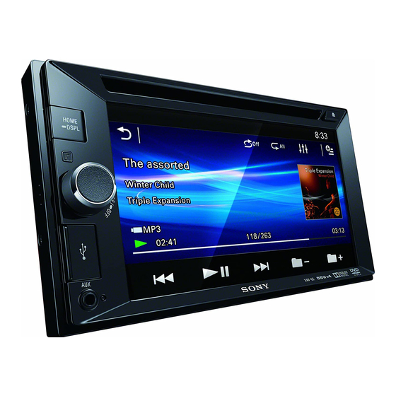
Sony XAV-65 Service Manual
Hide thumbs
Also See for XAV-65:
- Operating instructions manual (76 pages) ,
- Brochure & specs (4 pages) ,
- Operating instructions manual (72 pages)
Table of Contents
Advertisement
Quick Links
SERVICE MANUAL
Ver. 1.2 2014.12
(US and Canadian models only)
FOR UNITED STATES CUSTOMERS. NOT
APPLICABLE IN CANADA, INCLUDING IN THE
PROVINCE OF QUEBEC.
POUR LES CONSOMMATEURS AUX ÉTATS-
UNIS. NON APPLICABLE AU CANADA, Y
COMPRIS LA PROVINCE DE QUÉBEC.
AUDIO POWER SPECIFICATIONS
CEA2006 Standard
Power Output: 17 Watts RMS × 4 at
4 Ohms < 1% THD+N
SN Ratio: 80 dBA
(reference: 1 Watt into 4 Ohms)
Monitor section
Display type: Wide LCD color monitor
Dimensions: 6.2 in
System: TFT active matrix
Number of pixels:
1,152,000 pixels (800 × 3 (RGB) × 480)
Color system:
PAL/NTSC/SECAM/PAL-M automatic select
Tuner section (US, Canadian and E (NTSC) models)
FM
Tuning range:
87.5 – 107.9 MHz
FM tuning step: 100 kHz/200 kHz switchable
(E (NTSC) model only)
Antenna (aerial) terminal:
External antenna (aerial) connector
Intermediate frequency: 150 kHz
Usable sensitivity: 10 dBf
Selectivity: 70 dB at 400 kHz
Signal-to-noise ratio: 70 dB (mono)
Separation at 1 kHz: 30 dB
Frequency response: 20 - 15,000 Hz
AM
530 – 1,710 kHz
Tuning range:
Antenna (aerial) terminal:
External antenna (aerial) connector
Intermediate frequency:
9,267.5 kHz or 9,257.5 kHz/5 kHz
Sensitivity: 44 μV
9-893-911-03
Sony Corporation
2014L33-1
©
2014.12
Published by Sony Techno Create Corporation
Model Name Using Similar Mechanism
Mechanism Type
SPECIFICATIONS
Tuner section (AEP, Russian, UK, E (PAL),
Saudi Arabia, Indian and Australian models)
FM
Tuning range: 87.5 – 108.0 MHz
Antenna (aerial) terminal:
External antenna (aerial) connector
Intermediate frequency: 150 kHz
Usable sensitivity: 10 dBf
Selectivity: 70 dB at 400 kHz
Signal-to-noise ratio: 70 dB (mono)
Separation at 1 kHz: 30 dB
Frequency response: 20 - 15,000 Hz
AM
Tuning range: 531 – 1,602 kHz
Antenna (aerial) terminal:
External antenna (aerial) connector
Intermediate frequency:
9,267 kHz or 9,258 kHz/4.5 kHz
Sensitivity: 44 μV
DVD/CD Player section
Signal-to-noise ratio: 80 dB
Frequency response: 20 – 20,000 Hz
Wow and flutter: Below measurable limit
Harmonic distortion: 0.05%
Region code: Labeled on the bottom of the unit
USB Player section
Interface: USB (Full-speed)
Maximum current: 1 A
Power amplifier section
Outputs: Speaker outputs
Speaker impedance: 4 – 8 ohms
Maximum power output: 55 W × 4 (at 4 ohms)
General
Outputs:
Video output terminal (rear)
Audio output terminals (front, rear/sub
switchable)
Power antenna (aerial)/Power amplifier control
terminal (REM OUT)
XAV-65
US Model
Canadian Model
AEP Model
UK Model
E Model
Australian Model
NEW
DR28N-ABB-YG
Inputs:
Illumination control terminal
Remote controller input terminal
Antenna (aerial) input terminal
Parking brake control terminal
Reverse input terminal
Camera input terminal
AUX audio input terminal (Front)
AUX Audio/Video input terminal (Rear)
USB port
External input terminal (E (PAL), Saudi Arabia,
Indian and Australian models only)
Power requirements: 12 V DC car battery
(negative ground (earth))
Dimensions: Approx. 178 mm × 101.5 mm × 169 mm
(7
1
/
× 4 × 6
3
/
in) (w/h/d)
8
4
Mounting dimensions (Except AEP and UK models):
Approx. 178 mm × 100 mm × 165 mm
(7
1
/
× 4 × 6
1
/
in) (w/h/d)
8
2
Mounting dimensions (AEP and UK models):
Approx. 182 mm × 110.6 mm × 159 mm
(7
1
/
× 4
3
/
× 6
3
/
in) (w/h/d)
4
8
8
Mass: Approx. 1.6 kg (3 lb 9 oz)
Package contents:
Parts for installation and connections (1 set)
Remote Commander: RM-X170 (E (NTSC) and
Indian models only)
Design and specifications are subject to change
without notice.
Region code
The region system is used to protect software
copyrights.
The region code is located on the bottom of the
unit, and only DVDs labeled with an identical region
code can be played on this unit.
DVDs labeled
can also be played.
If you try to play any other DVD, the message
[Playback prohibited by region code.] will appear
on the monitor screen. Depending on the DVD, no
region code may be labeled even though playing
the DVD is prohibited by area restrictions.
AV CENTER
Advertisement
Table of Contents

Related Manuals for Sony XAV-65


Summary of Contents for Sony XAV-65
- Page 1 Intermediate frequency: the DVD is prohibited by area restrictions. Power antenna (aerial)/Power amplifier control AV CENTER 9,267.5 kHz or 9,257.5 kHz/5 kHz terminal (REM OUT) Sensitivity: 44 μV 9-893-911-03 Sony Corporation 2014L33-1 © 2014.12 Published by Sony Techno Create Corporation...
-
Page 2: Table Of Contents
LES DIAGRAMMES SCHÉMATIQUES ET LA LISTE DES PIÈCES SONT CRITIQUES POUR LA SÉCURITÉ DE FONC- TIONNEMENT. NE REMPLACER CES COMPOSANTS QUE PAR DES PIÈCES SONY DONT LES NUMÉROS SONT DON- NÉS DANS CE MANUEL OU DANS LES SUPPLÉMENTS PUBLIÉS PAR SONY. -
Page 3: Servicing Notes
XAV-65 Ver. 1.1 SECTION 1 SERVICING NOTES Replacing the lithium battery of the NOTES ON HANDLING THE OPTICAL PICK-UP remote commander BLOCK OR BASE UNIT (E (NTSC) and Indian models only) Under normal conditions, the battery will last The laser diode in the optical pick-up block may suffer electro- approximately 1 year. - Page 4 XAV-65 Ver. 1.1 NOTE OF REPLACING THE CHASSIS MAIN ASSY (CHA1) 1. Press the [ V ] or [ v ] button, and select the alphanumeric char- When the chassis MAIN assy (CHA1) is replaced, the destination acter of “0 to F”.
- Page 5 XAV-65 Ver. 1.2 DISTINGUISHING BETWEEN THE FORMER AND NEW TYPES OF THE COMPLETE KEY BOARD, GUIDE ASSY, AND FRONT PANEL ASSY (Except Saudi Arabia model) The complete KEY board, guide assy, and front panel assy built into this unit have been changed from midway of production.
-
Page 6: General
XAV-65 SECTION 2 This section is extracted GENERAL from instruction manual. (US and Canadian models) À la borne +12 V qui est alimentée lorsque la Français English To a car’s illumination signal clé de contact est sur la position accessoires Español... - Page 7 Es posible que pueda instalar la unidad en algunos automóviles japoneses sin el soporte. En caso de que no pudiera, consulte al distribuidor Sony más cercano. Cuando monte la unidad en los soportes preinstalados de su automóvil, utilice los tornillos...
- Page 8 XAV-65 (AEP and UK models) English Español Italiano Cautions Precauciones Attenzione Run all ground (earth) leads to a common ground Conecte todos los cables de conexión a masa a un Portare tutti i cavi di massa a un punto di massa (earth) point.
- Page 9 In tal direct sunlight or near heater ducts. Attenzione Precaución consulte con el distribuidor Sony más cercano. caso, rivolgersi al più vicino rivenditore Sony. Reset button Use only the supplied mounting hardware for a safe...
- Page 10 XAV-65 (Russian model) Схема підключення Русский Схема подключения Українська До шнура вимикача стоянкового гальма Внимание К шнуру выключателя стояночного Увага! Місце кріплення шнура вимикача стоянкового гальма тормоза залежить від автомобіля. Докладніше див. у розділі Подведите все провода заземления к одной...
- Page 11 -B Установка устройства в японском Цей пристрій можна встановлювати в деякі автомобиле автомобілі японських марок без кронштейна. Якщо це неможливо, зверніться до дилера Sony. В некоторых моделях японских автомобилей это устройство можно установить без использования кронштейна. Если вам не удается это сделать, обратитесь...
- Page 12 XAV-65 Ver. 1.1 (E (NTSC), E (PAL), Saudi Arabia, Indian and Australian models) Al cable de control de la antena motorizada o Notes on the control and power supply leads ﻓﺎرﺳﯽ ﻣﺨﻄﻂ اﻟﺘﻮﺻﻴﻞ Cautions REM OUT lead (blue/white striped) supplies +12 V DC when you turn al cable de fuente de alimentación del...
- Page 13 T for automóviles japoneses sin el soporte. En caso de que TOYOTA, M for MITSUBISHI and N for NISSAN. no pudiera, consulte al distribuidor Sony más cercano. Dashboard Notes Cuando monte la unidad en los soportes...
-
Page 14: Disassembly
XAV-65 SECTION 3 DISASSEMBLY • This set can be disassembled in the order shown below. 3-1. DISASSEMBLY FLOW 3-2. MINI FUSE (BLADE TYPE) (10 A) (F1), COVER (Page 14) 3-3. FRONT PANEL BLOCK (Page 15) 3-4. DVD DECK ASSY 3-5. GUIDE ASSY... -
Page 15: Front Panel Block
XAV-65 3-3. FRONT PANEL BLOCK Note 1: When installing the sheet (KEY protection), Sheet (KEY protection) setting paste the sheet (KEY protection) after aligned with the edge of the hole. Note 2: Arrange the touch panel flexible Do not align with the silk print. -
Page 16: Dvd Deck Assy (Dr28N-Abb-Yg) (Dvm1)
XAV-65 Ver. 1.1 3-4. DVD DECK ASSY (DR28N-ABB-YG) (DVM1) 1 screw deck assy (DR28N-ABB-YG) (M2.6 5 B/F) (DVM1) Note: When installing the flexible flat cable, insert straight to the connector and lock a connector completely. No slanting after insertion. Insert is straight to the interior. -
Page 17: Key Board
XAV-65 Ver. 1.1 3-6. KEY BOARD Note 1: When the complete KEY board is replaced, refer Note 2: When installing the flexible board, insert straight to the connector. to “FLICKER ADJUSTMENT” on page 18. No slanting after insertion. Insert is straight to the interior. -
Page 18: Electrical Adjustment
XAV-65 SECTION 4 ELECTRICAL ADJUSTMENT MONITOR SECTION If any of the following parts was replaced, execute the “Flicker Adjustment” as mentioned below. • CHASSIS MAIN ASSY (CHA1) • FRONT PANEL ASSY (FP1) • COMPLETE KEY BOARD Preparation: • Remote commander (RM-X170) FLICKER ADJUSTMENT 1. -
Page 19: Exploded View
XAV-65 Ver. 1.1 SECTION 5 EXPLODED VIEW Note: • -XX and -X mean standardized parts, so • Color Indication of Appearance Parts Ex- The components identifi ed by mark 0 they may have some difference from the ample: or dotted line with mark 0 are critical for original one. -
Page 20: Accessories
XAV-65 Ver. 1.1 SECTION 6 ACCESSORIES Ref. No. Part No. Description Remark ACCESSORIES ************ 1-487-638-13 REMOTE COMMANDER (RM-X170) (E (NTSC), IND) 4-484-834-13 MANUAL, INSTRUCTION (ENGLISH, FRENCH, SPANISH) (US, CND) 4-484-834-23 MANUAL, INSTRUCTION (ENGLISH, SPANISH) CONNECTING CABLE (SW) (E (NTSC)) 4-484-834-33... - Page 21 XAV-65 MEMO...
- Page 22 XAV-65 REVISION HISTORY Checking the version allows you to jump to the revised page. Also, clicking the version at the top of the revised page allows you to jump to the next revised page. Ver. Date Description of Revision 2013.11 2014.10...