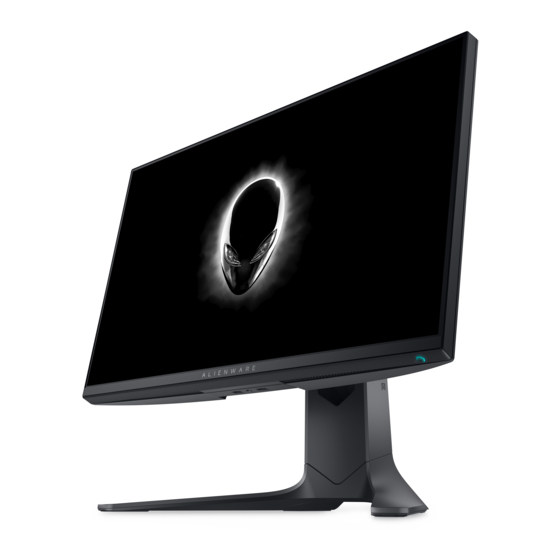
Summary of Contents for Dell AW2521HF
- Page 1 Simplified Service Manual–AW2521HF/ AW2521HFL/ AW2521HFA/ AW2521HFLA Version: 01 Date:2021/08/23 - 1 -...
-
Page 2: Table Of Contents
Content Index 1. General Safety Instructions ..................3 1.1 SAFETY: General Safety ..................3 1.2 SAFETY: General Power Safety ................5 2. Exploded view diagram with list of items ..............6 3. Wiring connectivity diagram ..................7 4. Disassembly and Assembly Procedures ..............8 4.1 Disassembly SOP .................... -
Page 3: General Safety Instructions
IMPORTANT NOTICE FOR USE IN HEALTHCARE ENVIRONMENTS: Dell products are not medical devices and are not listed under UL or IEC 60601 (or equivalent). As a result, they must not be used within 6 feet of a patient or in a manner that directly or indirectly contacts a patient 1.1 SAFETY: General Safety... - Page 4 When operating your equipment: Do not use your equipment in a wet environment, for example, near a bath tub, sink, or swimming pool or in a wet basement. Do not use AC powered equipment during an electrical storm. Battery powered devices may be used if all cables have been disconnected.
-
Page 5: Safety: General Power Safety
Be sure to grasp the plug, not the cable, when disconnecting equipment from an electric socket. If your equipment uses an AC adapter: Use only the Dell provided AC adapter approved for use with this device. Use of another AC adapter may cause a fire or explosion. ... -
Page 6: Exploded View Diagram With List Of Items
2. Exploded view diagram with list of items Item Description Q'ty Item Description Q'ty Panel TAPE CONDUCTIVE 90x10 GASKET 20*13*12 BTN PWR PCBA CTRL BD PCBA LENS BD PCBA CTRL+KEY BD MYLAR CTRL-BD FFC 8P P1 645MM CTRL FFC 8P P1 685MM LENS PCBA LED DRV BD ASSY SHD MAIN ASSY CVR-IO... -
Page 7: Wiring Connectivity Diagram
3. Wiring connectivity diagram Wire 2 Wire 3 Wire 4 Wire 5 Wire 6 FFC 1 FFC 2 FFC 3 FFC 4 Wire 1 FFC 5 - 7 -... -
Page 8: Disassembly And Assembly Procedures
4) Cleaning cloth 5) ESD protection Note: The disassembly procedure for AW2521HF/ AW2521HFL/ AW2521HFA/ AW2521HFLA is the same. The difference is only the appearance color. The actual color of AW2521HF/ AW2521HFA is black, but AW2518HFL/ AW2521HFLA is Lunar Light. Item... - Page 9 1. Press and hold the stand release button 2. Lift the stand up and away from the monitor 1. Unlock 4 screws on 1.Philips- Rear Cover head screwdriv 2. Use hands or scraper bar to disassemble (Torsion Rear Cover from of RC monitor screw:...
- Page 10 1. Tear off mylar and all tapes from Backlight Wire on Main SHD 2. Unplug Backlight Wire from SPS BD 3. Unplug “Power LENS FFC cable” from I/F BD and tear off “Power LENS FFC cable” from the panel 4. Unplug EDP FFC Cable between panel and I/F BD Unlock 1 screw on...
- Page 11 Disassemble I/F BD from Main SHD Disassemble wires from I/F BD Do not touch Disassemble SPS BD Philips- from Main SHD and head component disassemble “AC screwdriver without Socket Wire” from wearing SPS BD (Torsion of insulating screw: gloves 8.5±1.0kg) when disassembli assembling...
-
Page 12: Assembly Sop
4) Cleaning cloth 5) ESD protection Note: The disassembly procedure for AW2521HF/ AW2521HFL/ AW2521HFA/ AW2521HFLA is the same. The difference is only the appearance color. The actual color of AW2521HF/ AW2521HFA is black, but AW2518HFL/ AW2521HFLA is Lunar Light. Item... - Page 13 1. Lock 8 PCBA screws Philips-head screwdriver 2. Insert “FFC EDP” to I/F BD and fix it on I/F BD by 1 (Torsion of tape PCBA screw: 8.5±1.0kg Torsion of FFC EDP 51P Docking BD screw: 3. Insert Docking BD wire to 8.5±1.0Kg) Docking BD, then, assemble Docking BD to...
- Page 14 1. Insert “I/F BD to LED Driver BD wire” to I/F BD and paste 1 adhesive tape to fix it (See red mark) 2. Insert CTRL FFC Cable to I/F BD Note: The last piece of double- sided tape needs to be pasted on Main SHD 3.
-
Page 15: Trouble Shooting Instructions
5. Trouble shooting instructions - 15 -... - Page 16 - 16 -...
- Page 17 - 17 -...
- Page 18 - 18 -...
- Page 19 - 19 -...
- Page 20 - 20 -...


