Table of Contents
Troubleshooting

Related Manuals for Miller D-74 MPa Plus


Summary of Contents for Miller D-74 MPa Plus
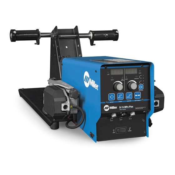
- Page 1 OM-243 347G 2014−07 Processes MIG (GMAW) Welding MIG (GMAW-P) Welding Flux Cored (FCAW) Welding (Gas- And Self-Shielded) Description Wire Feeder Aluminum Push/Pull Capable D-74 MPa Plus File: MIG (GMAW) Visit our website at www.MillerWelds.com...
- Page 2 We know you don’t have time to do it any other way. That’s why when Niels Miller first started building arc welders in 1929, he made sure his products offered long-lasting value and superior quality.
-
Page 3: Table Of Contents
TABLE OF CONTENTS SECTION 1 − SAFETY PRECAUTIONS - READ BEFORE USING ....... . . 1-1. - Page 4 DECLARATION OF CONFORMITY for European Community (CE marked) products. MILLER Electric Mfg. Co., 1635 Spencer Street, Appleton, WI 54914 U.S.A. declares that the product(s) identified in this declaration conform to the essential requirements and provisions of the stated Council Directive(s) and Standard(s).
-
Page 5: Section 1 − Safety Precautions - Read Before Using
SECTION 1 − SAFETY PRECAUTIONS - READ BEFORE USING som 2013−09 Protect yourself and others from injury — read, follow, and save these important safety precautions and operating instructions. 1-1. Symbol Usage DANGER! − Indicates a hazardous situation which, if Indicates special instructions. - Page 6 D Remove stick electrode from holder or cut off welding wire at FUMES AND GASES can be hazardous. contact tip when not in use. D Wear body protection made from durable, flame−resistant material Welding produces fumes and gases. Breathing (leather, heavy cotton, wool). Body protection includes oil-free these fumes and gases can be hazardous to your clothing such as leather gloves, heavy shirt, cuffless trousers, high health.
-
Page 7: Additional Symbols For Installation, Operation, And Maintenance
1-3. Additional Symbols For Installation, Operation, And Maintenance FIRE OR EXPLOSION hazard. MOVING PARTS can injure. D Do not install or place unit on, over, or near D Keep away from moving parts such as fans. combustible surfaces. D Keep all doors, panels, covers, and guards D Do not install unit near flammables. -
Page 8: California Proposition 65 Warnings
1-4. California Proposition 65 Warnings Welding or cutting equipment produces fumes or gases This product contains chemicals, including lead, known to which contain chemicals known to the State of California to the state of California to cause cancer, birth defects, or other cause birth defects and, in some cases, cancer. -
Page 9: Section 2 − Consignes De Sécurité − Lire Avant Utilisation
SECTION 2 − CONSIGNES DE SÉCURITÉ − LIRE AVANT UTILISATION fre_som_2013−09 Pour écarter les risques de blessure pour vous−même et pour autrui — lire, appliquer et ranger en lieu sûr ces consignes relatives aux précautions de sécurité et au mode opératoire. 2-1. - Page 10 D Ne pas raccorder plus d’une électrode ou plus d’un câble de D Avoir recours à des écrans protecteurs ou à des rideaux pour masse à une même borne de sortie de soudage. Débrancher le protéger les autres contre les rayonnements les éblouissements câble pour le procédé...
-
Page 11: Dangers Supplémentaires En Relation Avec L'installation, Le Fonctionnement Et La Maintenance
LES BOUTEILLES peuvent exploser DES PIECES DE METAL ou DES si elles sont endommagées. SALETES peuvent provoquer des blessures dans les yeux. Les bouteilles de gaz comprimé contiennent du gaz sous haute pression. Si une bouteille est D Le soudage, l’écaillement, le passage de la endommagée, elle peut exploser. - Page 12 LES CHARGES ÉLECTROSTATI- RAYONNEMENT HAUTE QUES peuvent endommager les cir- FRÉQUENCE (H.F.) risque cuits imprimés. provoquer des interférences. D Établir la connexion avec la barrette de terre D Le rayonnement haute fréquence (H.F.) peut avant de manipuler des cartes ou des pièces. provoquer des interférences avec les équi- pements de radio−navigation et de com- D Utiliser des pochettes et des boîtes antista-...
-
Page 13: Proposition Californienne 65 Avertissements
2-4. Proposition californienne 65 Avertissements Les équipements de soudage et de coupage produisent des Ce produit contient des produits chimiques, notamment du fumées et des gaz qui contiennent des produits chimiques plomb, dont l’État de Californie reconnaît qu’ils provoquent dont l’État de Californie reconnaît qu’ils provoquent des mal- des cancers, des malformations congénitales ou d’autres formations congénitales et, dans certains cas, des cancers. - Page 14 OM-243 347 Page 10...
-
Page 15: Section 3 − Definitions
SECTION 3 − DEFINITIONS 3-1. Additional Safety Symbols And Definitions Some symbols are found only on CE products. Warning! Watch Out! There are possible hazards as shown by the symbols. Safe1 2012−05 Do not discard product (where applicable) with general waste. Reuse or recycle Waste Electrical and Electronic Equipment (WEEE) by disposing at a designated collection facility. -
Page 16: Miscellaneous Symbols And Definitions
Do not weld on drums or any closed containers. Safe64 2012−06 Do not remove or paint over (cover) the label. Safe20 2012−05 Drive rolls can injure fingers. Safe32 2012−05 Welding wire and drive parts are at welding voltage during operation − keep hands and metal objects away. Safe33 2012−05 Wear hat and safety glasses. -
Page 17: Section 4 − Specifications
SECTION 4 − SPECIFICATIONS 4-1. Serial Number And Rating Label Location The serial number and rating information for this product is located on the rear panel. Use rating label to determine input power requirements and/or rated output. For future reference, write serial number in space provided on back cover of this manual. 4-2. -
Page 18: Section 5 − Installation
SECTION 5 − INSTALLATION 5-1. Site Selection Do not put feeder where welding wire hits cylinder. Do not move or operate equipment where it could tip. Wire Feeder Wire Spool/Reels Gas Cylinder w/Hose And Regulator (Customer Supplied) Shielding gas pressure not to exceed 100 psi (689 kPa). -
Page 19: Equipment Connection Diagrams
5-2. Equipment Connection Diagrams Welding Power Source Select welding power source according to Section 6-11. Contactor Control/Power Cord Positive (+) Weld Cable Negative (−) Weld Cable Workpiece Welding Gun Wire Feeder Gas Hose Gas Cylinder and Regulator (Customer Supplied) Shielding gas pressure not to exceed 100 psi (689 kPa). -
Page 20: Rear Panel Connections And Rotating Drive Assembly
5-3. Rear Panel Connections And Rotating Drive Assembly 14-Pin Control Cable - 15 Ft (4.6 m) Shielding Gas Valve Fittings Requires fitting with 5/8-18 right- hand threads. Connect customer- supplied gas hose. Weld Cable Terminal Jumper Weld Cable Weld Cable Drive Assembly Drive Assembly Rotation Knob... -
Page 21: 14-Pin Plug Information For Connecting Wire Feeder To Power Source
5-4. 14-Pin Plug Information For Connecting Wire Feeder To Power Source Pin* Pin Information 24 volts AC with respect to socket G. Contact closure to A completes 24 volts AC contactor control circuit. Circuit common for 24 volts AC circuit. +10 volts DC input from power source to wire feeder with respect to socket D. -
Page 22: Installing Welding Gun
5-6. Installing Welding Gun Power Clamp Knob Gun Locking Tab Power Pin Groove Gun Connection End Installing gun with Accu-Mate connection Loosen power clamp knob to allow power pin of gun to clear the gun locking tab. Push power pin into power clamp as far as possible to align the groove in the power pin of the gun with the gun locking tab. -
Page 23: Installing And Threading Welding Wire
5-7. Installing And Threading Welding Wire Install wire guides and Install wire spool. Adjust tension nut so anti-wear guide. wire is taut when wire feed stops. Install drive rolls. Pressure Scale Pressure Pressure Indicator Adjust Rear Pressure Rolls Adjust Front Rolls No Wire Slip Wire Slips... -
Page 24: Section 6 − Operation
SECTION 6 − OPERATION 6-1. Power Switch Power Switch Ref. 245 239-A 6-2. Jog/Purge Switch Jog/Purge Switch Ref. 245 239-A Pressing the Jog/Purge switch allows the op- mum of two minutes. If the gun trigger is still control when the unit is jogging wire. The erator to jog wire without energizing the weld activated after two minutes, the jog opera- unit displays jog speed when the unit is be-... -
Page 25: Front Panel Controls
6-3. Front Panel Controls Adjust Control Left Adjust Control Right Crater Push Button (See Section 6-9) (See Section 6-6) (See Section 6-6) Start Push Button (See Section 6-8) Left Display (See Section 6-4) Left/Right Display Push Button Setup Push Button Right Display (See Section 6-5) (See Section 6-10) (See Section 6-7) -
Page 26: Left Display
6-4. Left Display Left Side Schedule A LED The unit displays both preset and actual arc To set the correct voltage range for a par- voltage. When the unit is in a welding state, Left Side Schedule B LED ticular power source, see Section 6-11 − actual arc voltage is displayed. -
Page 27: Adjust Control Left/Right
6-6. Adjust Control Left/Right Adjust Control Use Adjust control to change vari- ous parameters or menu items. Use left control to adjust volts or arc length. Use right control to adjust amper- age or wire feed speed. 6-7. Setup Push Button Setup Push Button Setup LED When the Setup button is pressed,... -
Page 28: Left/Right Display Push Button
6-10. Left/Right Display Push Button Left/Right Display Push Button Left Side Activate LED Right Side Activate LED Press button to activate left or right side. 6-11. Power Source Selection Menu Left Display Right Display When the feeder is turned on, the Power Source Selection Menu allows the operator to se- lect a default power source. -
Page 29: Operational Terms
6-12. Operational Terms The following is a list of terms and their definitions as they apply to this wire feeder: General Terms: Cold Wire Jog Feeding wire without contactor or gas valve being energized. Sequence A portion of the weld program, such as preflow, run-in, start, weld, crater, burnback, and postflow. Weld Program A group of sequences that make up a weld cycle. -
Page 30: Section 7 − Setting Sequence Parameters
SECTION 7 − SETTING SEQUENCE PARAMETERS 7-1. Sequence Parameters In A Program Sequence Parameters Volts Seconds 1. Preflow 0-5.0 2. Run-In x0.1-x1.00 3. Start .1-.5 4. Weld 0-100.0 5. Crater 0.00-5.00 6. Postflow 0.0-10.0 X = Setting available. Weld Time Crater Time Preflow... -
Page 31: Section 8 − Programming
SECTION 8 − PROGRAMMING 8-1. Setup Menu To enter the SETUP MENU press and re- tion is active, the wire feeder will continue for each schedule. This allows the op- erator to remotely change the weld lease the SETUP button. The SETUP feeding wire until the trigger is pressed and process at the wire feeder and power MENU INDICATOR and the SETUP... -
Page 32: Setup Menu Level 2
8-2. Setup Menu Level 2 To enter the SETUP MENU LEVEL 2 press INDICATOR illuminated. Sets the minimum (PROF) will appear in the Setup Menu. Pro- and hold the SETUP button. The SETUP voltage. Range of this setting is dependent file Pulse parameters cannot be adjusted MENU INDICATOR and the SETUP when Parameter Lock is set to (ON). -
Page 33: Setting A Start Sequence In Synergic Pulse
8-3. Setting A Start Sequence In Synergic Pulse To turn on a Start sequence, press the To exit the START MENU, press and re- Example: If the weld arc length is set to 50 START button. START lease the START button. and ARC.L is X0.50, the Start Arc Length is INDICATOR will illuminate indicating Start Items that can be adjusted in this menu are:... -
Page 34: Setting A Start Sequence In Non−Synergic Pulse Or Mig
8-4. Setting A Start Sequence In Non−Synergic Pulse Or MIG To turn on a Start sequence, press the Knob to change menu item values shown When MIG is selected in Setup Menu START button. START in the RIGHT DISPLAY. Level 1 the start arc length setting will INDICATOR will illuminate indicating Start be replaced by Start Voltage (VOLT). -
Page 35: Setting A Crater Fill Sequence In Synergic Pulse
8-5. Setting A Crater Fill Sequence In Synergic Pulse To turn on Crater Fill, press the CRATER lease the CRATER button. When the PULS option in the SETUP button. The CRATER ON INDICATOR will MENU LEVEL 2 is set to VOLT, the Items that can be adjusted in this menu are: illuminate indicating Crater Fill is active. -
Page 36: Setting A Crater Fill Sequence In Non−Synergic Pulse Or Mig
8-6. Setting A Crater Fill Sequence In Non−Synergic Pulse Or MIG To turn on Crater Fill, press the CRATER To exit the CRATER MENU press and re- ting is dependent on the power source or button. The CRATER ON INDICATOR will lease the CRATER button. -
Page 37: Profile Pulse
8-7. Profile Pulse Profile Pulse optimizes Aluminum weld set to (YES). See section 8-2. unit is set to for welding. Range of this set- bead appearance by producing welds with ting is (X0.00 to X0.30). Example: If the wire Profile Pulse Items that can be adjusted in consistently spaced ripple patterns, similar feed speed is 200 and (P.WFS) is set to the Setup Menu are:... -
Page 38: Section 9 − Maintenance & Troubleshooting
SECTION 9 − MAINTENANCE & TROUBLESHOOTING 9-1. Routine Maintenance Disconnect power before maintaining. n = Check ~ = Clean l = Replace Every Spool of Wire or Wire Change n~ Gun Liner Every Months l Unreadable Labels ~ Weld Terminals nl Weld Cable l Cracked Parts n 14-Pin Cord... -
Page 39: Troubleshooting
9-3. Troubleshooting Disconnect power before troubleshooting. Trouble Remedy Secure plug from gun control cable into Gun Control receptacle on feeder (see Section 5-6). Pressing gun trigger does not energize feeder. Shielding gas does not flow and Have nearest Factory Authorized Service Agent check optional water flow switch, if applicable. wire feeder does not feed. -
Page 40: Section 10 − Electrical Diagram
SECTION 10 − ELECTRICAL DIAGRAM Figure 10-1. Circuit Diagram OM-243 347 Page 36... - Page 41 242 890-D OM-243 347 Page 37...
-
Page 42: Section 11 − Parts List
SECTION 11 − PARTS LIST Hardware is common and not available unless listed. Fig.11-3 Fig.11-2 245 242-A Figure 11-1. Main Assembly OM-243 347 Page 38... - Page 43 Item Part Description Quantity Figure 11-1. Main Assembly ....159 647 Insulator, Motor Clamp ......... . .
- Page 44 Hardware is common and not available unless listed. 245 243-B Figure 11-2. Control Box Item Dia. Part Mkgs. Description Quantity Figure 11-2. Control Box (Figure 11-1 Item 22) ....204 722 Wrapper, Feeder .
- Page 45 Item Dia. Part Mkgs. Description Quantity Figure 11-2. Control Box (Figure 11-1 Item 22) (Continued) ....243 078 Panel, Front Feeder ..........
- Page 46 Hardware is common and not available unless listed. 20 12 See Table 11-1 For Drive Roll & Wire Guide Kits 245 244-A Figure 11-3. Drive Assembly, Wire Item Dia. Part Mkgs. Description Quantity Figure 11-3. Drive Assembly, Wire (Figure 11-1 Item 4) .
- Page 47 Item Dia. Part Mkgs. Description Quantity Figure 11-3. Drive Assembly, Wire (Continued) ....182 156 ..Spring, Cprsn ..........
- Page 48 Table 11-1. Drive Roll And Wire Guide Kits OM-243 347 Page 44...
- Page 49 Notes Start Your Professional Over 80,000 trained 400 Trade Square East, Troy, Ohio 45373 Welding Career Now! since 1930! 1-800-332-9448 www.welding.org...
- Page 50 Notes...
- Page 51 Effective January 1, 2014 (Equipment with a serial number preface of ME or newer) This limited warranty supersedes all previous Miller warranties and is exclusive with no other guarantees or warranties expressed or implied. Warranty Questions? LIMITED WARRANTY − Subject to the terms and conditions below, 6 Months —...
- Page 52 Contact the Delivering Carrier to: File a claim for loss or damage during shipment. For assistance in filing or settling claims, contact your distributor and/or equipment manufacturer’s Transportation Department. © ORIGINAL INSTRUCTIONS − PRINTED IN USA 2014 Miller Electric Mfg. Co. 2014−01...