
Related Manuals for Miller DYNASTY DX


Summary of Contents for Miller DYNASTY DX
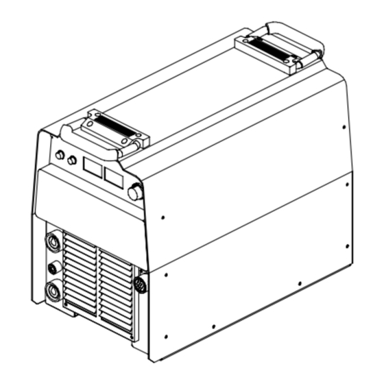
- Page 1 TM-357A June 1999 Eff. w/Serial Number KH384382 Processes TIG (GTAW) Welding Stick (SMAW) Welding Description Arc Welding Power Source Dynasty DX With Auto-Link Visit our website at www.MillerWelds.com...
-
Page 2: Table Of Contents
TABLE OF CONTENTS SECTION 1 – SAFETY PRECAUTIONS FOR SERVICING ........1-1. -
Page 3: Section 1 - Safety Precautions For Servicing
D Do not place unit on, over, or near combustible D Keep away from moving parts such as fans. surfaces. D Keep all doors, panels, covers, and guards D Do not service unit near flammables. closed and securely in place. Dynasty DX TM-357 Page 1... -
Page 4: Emf Information
OVER- READ INSTRUCTIONS. HEATING. D Use MILLER Testing Booklet (Part No. 150 D Allow cooling period; follow rated duty cycle. 853) when servicing this unit. D Reduce current or reduce duty cycle before D Consult the Owner’s Manual for welding safety starting to weld again. -
Page 5: Section 2 - Installation
250 A @ 40% Duty Cycle For AC 200 A @ 40% Duty Cycle For DC 4 Minutes Welding 6 Minutes Resting Overheating A or V Reduce Duty Cycle Minutes sduty1 5/95 / SA-185 794 Dynasty DX TM-357 Page 3... -
Page 6: Volt-Ampere Curves
2-3. Volt-Ampere Curves Volt-ampere curves show minimum and maximum voltage and amper- age output capabilities of unit. Curves of other settings fall be- tween curves shown. SA-185 793 / SA-186 294 TM-357 Page 4 Dynasty DX... -
Page 7: Selecting A Location
Y Special installation may be required where gasoline or volatile liquids are present – see NEC Article 511 or CEC Location Section 20. 18 in (460 mm) 18 in (460 mm) loc_2 3/96 - ST-801 708-A Dynasty DX TM-357 Page 5... -
Page 8: Weld Output Terminals And Selecting Cable Sizes
0 to +10 volts dc input command signal from remote control. Not used. Current feedback; +1 volt dc per 100 amperes. AMPERAGE Voltage feedback; +1 volt dc per 10 output VOLTAGE receptacle volts. Chassis common. *The remaining sockets are not used. TM-357 Page 6 Dynasty DX... -
Page 9: Breaker Cb1
Min Input Conductor Size In AWG/Kcmil Max Recommended Input Conductor Length In Feet 104 (32) 165 (50) 90 (27) 241 (74) (Meters) Min Grounding Conductor Size In AWG/Kcmil Reference: 1996 National Electrical Code (NEC). S-0092J Dynasty DX TM-357 Page 7... -
Page 10: Connecting Input Power
(L1, L2, L3) to line terminals. Y Always connect green wire to supply grounding termi- nal, never to a line terminal. Green Green Y Always connect grounding conductor first. = GND/PE Green input_2 3/96 - ST-801 709-A TM-357 Page 8 Dynasty DX... -
Page 11: Section 3 - Operation
Use control to select either of the GTAW tance, poor connections, etc. (TIG) welding process and polarity, or the Control sets length of time in seconds gas Ammeter (see Section 3-3) SMAW (Stick) welding process. flows after the welding stops. Dynasty DX TM-357 Page 9... -
Page 12: Ac/Balance Control
GTAW (TIG) With Lift-Arc Start – See Section Lift On Electrode Hot HF Remote GTAW (TIG) With HF Start – See Section 3-6 At Remote 14 Lift Remote GTAW (TIG) At Remote 14 Remote SMAW (Stick) At Remote 14 TM-357 Page 10 Dynasty DX... -
Page 13: Sequence Control
High frequency turns off when arc is started, and turns on whenever arc is broken to help Do NOT Strike Like A Match! restart arc. Ref. ST-156 279 Dynasty DX TM-357 Page 11... -
Page 14: Section 4 - Theory Of Operation
Postflow Time control R86, Se- quence Control switch S4, Process Select switch S3, Output Select Trigger Start Sequence Postflow switch S2, and Trigger Hold switch Hold Switch Amperage Control Control R86 Control R85 Switch S4 TM-357 Page 12 Dynasty DX... - Page 15 Couples HF energy created on PC7 to weld output circuit. 27 Electrode And Work Weld Output Receptacles AC Or DC Control Circuits Provide weld output and allow changing of output polarity. φ Power Weld Current Circuit ♦ Optional Dynasty DX TM-357 Page 13...
-
Page 16: Section 5 - Pre-Power Checklist
(+) and gate terminals. Resistance should be approximately 35 ohms. If results are in doubt, use an IGBT tester (MILLER Part No. 043 553) to test the SCR portion of SR1 as follows: Negative (–) A. Disconnect plug PLG13 –... -
Page 17: Tank Capacitor C1 And Input Capacitors
Y Read and follow safety information in Section 5-1 before proceeding. Test diodes individually according to the Diode Testing Procedure in the MILLER Testing Booklet (Part No. 150 853). Weld Output Receptacles Diodes D1, D2 Ref. SD-183 484 / ST-802 037... -
Page 18: Igbt Modules Pm1, Pm2, Pm3, Pm4
5-5. IGBT Modules PM1, PM2, PM3, PM4 Best Test For PM1 And PM2 (Use MILLER IGBT tester #043553) Y Read and follow safety information in Section 5-1 before proceeding. It is not necessary to remove interconnect- ing board PC2 to test the IGBT’s unless in- Control Board PC1 put capacitor C3 or C4 is shorted. - Page 19 Best Test For PM3 And PM4 (Use MILLER IGBT tester #043553) (Continued) Y Read and follow safety information in Section 5-1 before proceeding. Visually inspect PM3 and PM4 for damage. Disconnect gate lead plug PLG7 from receptacle RC7 on Control Board PC1 control board PC1.
-
Page 20: Diodes
2000 ohms ±10% in 230/460 volt models or 400 ohms ±10% in 460/575 volt models (ohms position). Check D3 and D4 on PC2 (diode test). Diode Diode Diode Diode Interconnecting Board PC2 ST-801 550 / SC-183 621-A TM-357 Page 18 Dynasty DX... -
Page 21: Contactors W1, W2 (230/460 V Models Only)
W1 and W2 to be sure contacts are not stuck shut (ohms position). Normally-Open Normally-Open Contacts Of 460 V Contacts Of 230 V Input Contactor W1 Auto-Link Contactor W2 Interconnecting Board PC2 ST-801 550 / SC-183 621-A Dynasty DX TM-357 Page 19... -
Page 22: Section 6 - Troubleshooting
SECTION 6 – TROUBLESHOOTING 6-1. Troubleshooting Table See Section 6-2 for test points and values and Sec- tion 10 for parts location. Use MILLER Testing Booklet (Part No. 150 853) when servicing this unit. Trouble Remedy Place line disconnect switch in On position (see Section 2-9). - Page 23 Reduce gas flow rate. Shield weld zone from drafts. Tungsten electrode oxidizing and not remaining bright after conclusion of weld. Increase postflow time. Check and tighten all gas fittings. Water in torch. Refer to torch manual. Dynasty DX TM-357 Page 21...
-
Page 24: Troubleshooting Circuit Diagram
460 V Input Contactor W1 230 V Auto-Link Contactor W2 See Section 4 See Section 6-6 See Section for RC1 for RT1, RT2 6-4 for information information PC1 data See Section 6-6 for PC3 data TM-357 Page 22 Dynasty DX... - Page 25 87 volts dc open-circuit voltage 325 volts dc * Pulsed dc values – measurements will vary. V17, A, B, C, D See Section 6-3 for waveforms A, B, C, D See Section 6-13 for PC6 information SD-189 922 Dynasty DX TM-357 Page 23...
-
Page 26: Waveforms For Sections 6-2
Amperes, 140 Hertz (Resistive Load) 2.5 µs 20V 2.5 ms 20 V C. AC Maximum Penetration, 30 Volts AC, D. DC, 28 Volts DC, 200 Amperes, (Resis- 250 Amperes, 140 Hertz (Resistive Load) tive Load) Test Equipment Needed: TM-357 Page 24 Dynasty DX... - Page 27 Notes Dynasty DX TM-357 Page 25...
-
Page 28: Control Board Pc1 Testing Information (Use With Section 6-5)
Control Board PC1 Receptacle RC1 Receptacle RC2 Receptacle RC3 Receptacle RC4 Receptacle RC5 Receptacle RC6 Receptacle RC7 Receptacle RC8 10 Receptacle RC9 11 Receptacle RC10 12 Receptacle RC11 Test Equipment Needed: ST-802 035 / SC-188 731-A TM-357 Page 26 Dynasty DX... -
Page 29: Control Board Pc1 Test Point Values
+1 volt dc input per 100 amperes of weld output Center tap for 18 volts ac secondary windings of control transformer T2 +15 volts dc Circuit common Circuit common for RC2-10 –24 volts dc with respect to pin RC2-9 with gas valve GS1 energized Dynasty DX TM-357 Page 27... - Page 30 750 Hz waveform with respect to pin RC9-3 (High Frequency gate pulses to HF board PC7) Not used Circuit common for pin RC9-1 (High Frequency gate pulses to HF board PC7) RC10 +15 volts dc with contactor energized, 0 volts dc at clamp shutdown Not used Not used Circuit common TM-357 Page 28 Dynasty DX...
-
Page 31: Display Board Pc3 Testing Information (Use With Section 6-7)
Connection point for thermistor RT2. 11 Output Switch S2 Display Board PC3 Voltmeter V Receptacle RC1 12 Amps Switch S1 Receptacle RC2 Ammeter A 13 Start/Crater Switch S4 Test Equipment Needed: ST- 802 035 / SC-189 538 Dynasty DX TM-357 Page 29... -
Page 32: Display Board Pc3 Test Point Values
0 to +10 volts dc input from min to max of Remote Amperage Adjustment Control 24 volts dc input, contactor 1, 2 Approximately 33 k ohms at 68°F (20°C) with thermistors plugged in 1, 2 Approximately 33 k ohms at 68°F (20°C) with thermistors plugged in TM-357 Page 30 Dynasty DX... -
Page 33: Interconnecting Board Pc2 Testing Information
26 in-lb when servicing IGBT’s PM1 and PM2. No test point values provided for this PC board. Interconnecting Board PC2 Receptacle RC1 Receptacle RC2 Receptacle RC3 Test Equipment Needed: ST-802 035 / Ref. SC-183 621-A Dynasty DX TM-357 Page 31... -
Page 34: High-Frequency Board Pc7 Testing Information (Use With Section 6-10)
See Section 6-10 for specific values during testing. High-Frequency Board PC7 Receptacle RC1 Receptacle RC2 Receptacle RC3 Receptacle RC4 Spark Gap—Set At 0.010 in (0.254 mm) Test Equipment Needed: ST-802 035 / SC-186 808-B TM-357 Page 32 Dynasty DX... -
Page 35: 6-10.High-Frequency Board Pc7 Test Point Values
740 Hz pulse waveform with respect to pin RC2-2 740 Hz pulse waveform with respect to pin RC2-1 Reference common Not used Do not measure – high voltage present. Do not measure – high voltage present. Dynasty DX TM-357 Page 33... -
Page 36: 6-11.Clamp Board Pc8 Testing Information (Use With Section 6-12)
Be sure plugs are secure before testing. See Section 6-12 for specific values during testing. Clamp Board PC8 Receptacle RC1 Receptacle RC2 Test Equipment Needed: ST-802 035 / SC-182 189-B TM-357 Page 34 Dynasty DX... -
Page 37: 6-12.Clamp Board Pc8 Test Point Values
–325 volts dc with respect to pin RC1-5 +325 volts dc with respect to pin RC2-2 –325 volts dc with respect to pin RC2-1 –325 volts dc with respect to pin RC2-4 +325 volts dc with respect to pin RC2-3 Dynasty DX TM-357 Page 35... -
Page 38: 6-13.Secondary Igbt Board Pc6 Testing Information (Use With Section 6-14)
Be sure plugs are secure before testing. See Section 6-14 for specific values during testing. Secondary IGBT Board PC6 Receptacle RC1 Test Equipment Needed: ST-802 037 / SC-182 193-A TM-357 Page 36 Dynasty DX... -
Page 39: 6-14.Secondary Igbt Board Pc6 Test Point Values With Contactor Off
Clamp voltage signal to board PC6 +15 volts dc with respect to pin RC1-1 Circuit common for pin RC1-8 –15 volts dc with respect to pin RC1-7 +15 volts dc with respect to pin RC1-10 Circuit common for pin RC1-9 Dynasty DX TM-357 Page 37... -
Page 40: Section 7 - Maintenance
115 volts ac duplex recep- tacle from overload. Circuit Breaker CB2 Prior to Serial No. KJ037293, CB2 protects the 24 volts ac portion of Remote 14 receptacle RC1 from overload. Press button to reset either circuit breaker. ST-801 866 TM-357 Page 38 Dynasty DX... -
Page 41: Voltmeter/Ammeter Help Displays
Indicates the left side of the unit has over- Indicates that the input voltage is too high Indicates an improper set-up. Check front heated. The unit has shut down to allow the and the unit has automatically shut down. panel. Dynasty DX TM-357 Page 39... -
Page 42: Measuring Input Capacitor Voltage
Measure the dc voltage across the positive (+) and negative (–) terminals until voltage drops to near 0 (zero) volts. Proceed with job inside unit. Reinstall case when finished. Tools Needed: 5/16 in ST-802 035 TM-357 Page 40 Dynasty DX... -
Page 43: Section 8 - High Frequency
HF or Line Disconnect Device 11 Lighting separate HF unit) Input Supply Wiring 12 Wiring Weld Cables 13 Water Pipes and Fixtures Torch 14 External Phone and Power Lines Work Clamp Workpiece Work Table S-0694 Dynasty DX TM-357 Page 41... -
Page 44: Correct Installation
A circle 50 ft (15 m) from center point in all 11 Overhead Door Track directions. Grounding Rod Ground the track. Weld Output Cables Consult the National Electrical Code for Keep cables short and close together. specifications. TM-357 Page 42 Dynasty DX... -
Page 45: Section 9 - Electrical Diagrams
The following is a list of all diagrams for models covered by this manual. Model Serial Or Style Number Circuit Diagram Wiring Diagram Dynasty DX (With Auto-Link) KH384382 thru KJ037292 SD-183 036-C SD-183 037-A♦♦ KJ037293 and following SD-189 922... - Page 46 Figure 9-1. Circuit Diagram For Dynasty DX Effective With Serial No. KH384382 Thru KJ037292 TM-357 Page 44 Dynasty DX...
- Page 47 SD-183 036-C Dynasty DX TM-357 Page 45...
- Page 48 Figure 9-2. Circuit Diagram For Dynasty DX Effective With Serial No. KJ037293 And Following TM-357 Page 46 Dynasty DX...
- Page 49 SD-189 922 Dynasty DX TM-357 Page 47...
- Page 50 Figure 9-3. Wiring Diagram For Dynasty DX Effective With Serial No. KJ037293 And Following TM-357 Page 48 Dynasty DX...
- Page 51 SD-183 037-B Dynasty DX TM-357 Page 49...
- Page 52 Figure 9-4. Circuit Diagram For Main Control Board PC1 Effective With Serial No. KJ037293 And Following (Part 1 Of 3) TM-357 Page 50 Dynasty DX...
- Page 53 SD-183 732-A Dynasty DX TM-357 Page 51...
- Page 54 Figure 9-5. Circuit Diagram For Main Control Board PC1 Effective With Serial No. KJ037293 And Following (Part 2 Of 3) TM-357 Page 52 Dynasty DX...
- Page 55 SD-183 732-A Dynasty DX TM-357 Page 53...
- Page 56 Figure 9-6. Circuit Diagram For Main Control Board PC1 Effective With Serial No. KJ037293 And Following (Part 3 Of 3) TM-357 Page 54 Dynasty DX...
- Page 57 SD-183 732-A Dynasty DX TM-357 Page 55...
- Page 58 SD-183 623 Figure 9-7. Circuit Diagram For Interconnecting Board PC2 Effective With Serial No. KH384382 And Following TM-357 Page 56 Dynasty DX...
- Page 59 Notes Dynasty DX TM-357 Page 57...
- Page 60 Figure 9-8. Circuit Diagram For Front Board PC3 Effective With Serial No. KH384382 And Following (Part 1 Of 2) TM-357 Page 58 Dynasty DX...
- Page 61 SD-189 540 Dynasty DX TM-357 Page 59...
- Page 62 Figure 9-9. Circuit Diagram For Front Board PC3 Effective With Serial No. KH384382 And Following (Part 2 Of 2) TM-357 Page 60 Dynasty DX...
- Page 63 SD-189 540 Dynasty DX TM-357 Page 61...
- Page 64 SD-188 015 Figure 9-10. Circuit Diagram For IGBT Single Board PC4, PC5 Effective With Serial No. KH518630 And Following TM-357 Page 62 Dynasty DX...
- Page 65 SD-182 195 Figure 9-11. Circuit Diagram For IGBT Double Board PC6 Effective With Serial No. KH384382 And Following Dynasty DX TM-357 Page 63...
- Page 66 SD-186 810 Figure 9-12. Circuit Diagram For HF Board PC7 Effective With Serial No. KH517737 And Following TM-357 Page 64 Dynasty DX...
- Page 67 SD-182 191-A Figure 9-13. Circuit Diagram For Clamp Board PC8 Effective With Serial No. KH384382 And Following Dynasty DX TM-357 Page 65...
- Page 68 Notes TM-357 Page 66 Dynasty DX...
- Page 69 TM-357A June 1999 Processes TIG (GTAW) Welding Stick (SMAW) Welding Description Arc Welding Power Source Dynasty DX Eff w/ KH384382 Thru KJ150395 For OM-357 (188 291) Revisions A thru D With Auto-Link Visit our website at www.MillerWelds.com...
-
Page 70: Section 10 - Parts List For Kh384382 Thru Kj150395
SECTION 10 – PARTS LIST For KH384382 Thru KJ150395 Hardware is common and not available unless listed. ST-801 870-A Figure 10-1. Main Assembly TM-357 Page 68 Dynasty DX... - Page 71 ..........Dynasty DX...
- Page 72 +When ordering a component originally displaying a precautionary label, the label should also be ordered. ♦Optional To maintain the factory original performance of your equipment, use only Manufacturer’s Suggested Replacement Parts. Model and serial number required when ordering parts from your local distributor. TM-357 Page 70 Dynasty DX...
- Page 73 Eff w/ KH384382 Thru KJ150395 Hardware is common and not available unless listed. 27-PC7 ST-801 871-A Figure 10-2. Windtunnels w/Components Dynasty DX TM-357 Page 71...
- Page 74 +When ordering a component originally displaying a precautionary label, the label should also be ordered. To maintain the factory original performance of your equipment, use only Manufacturer’s Suggested Replacement Parts. Model and serial number required when ordering parts from your local distributor. TM-357 Page 72 Dynasty DX...
- Page 75 TM-357A June 1999 Processes TIG (GTAW) Welding Stick (SMAW) Welding Description Arc Welding Power Source Dynasty DX Eff w/ KJ150396 And Following For OM-357 (188 291) Revision E With Auto-Link Visit our website at www.MillerWelds.com...
-
Page 76: Section 11 - Parts List For Kj150396 And Following
SECTION 11 – PARTS LIST For KJ150396 And Following Hardware is common and not available unless listed. ST-801 870-B Figure 11-1.Main Assembly TM-357 Page 74 Dynasty DX... - Page 77 ........TM-357 Page 75 Dynasty DX...
- Page 78 To maintain the factory original performance of your equipment, use only Manufacturer’s Suggested Replacement Parts. Model and serial number required when ordering parts from your local distributor. Hardware is common and not available unless listed. ST-801 871-A Figure 11-2.Windtunnels w/Components TM-357 Page 76 Dynasty DX...
- Page 79 +When ordering a component originally displaying a precautionary label, the label should also be ordered. To maintain the factory original performance of your equipment, use only Manufacturer’s Suggested Replacement Parts. Model and serial number required when ordering parts from your local distributor. TM-357 Page 77 Dynasty DX...
- Page 80 1635 West Spencer Street Appleton, WI 54914 USA International Headquarters–USA Phone: 920-735-4505 USA & Canada FAX: 920-735-4134 International FAX: 920-735-4125 European Headquarters – United Kingdom Phone: 44 (0) 1625-525556 FAX: 44 (0) 1625-537553 PRINTED IN USA 1998 Miller Electric Mfg. Co.