Table of Contents
Advertisement
Quick Links
For product information,
Owner's Manual translations,
and more, visit
www.MillerWelds.com
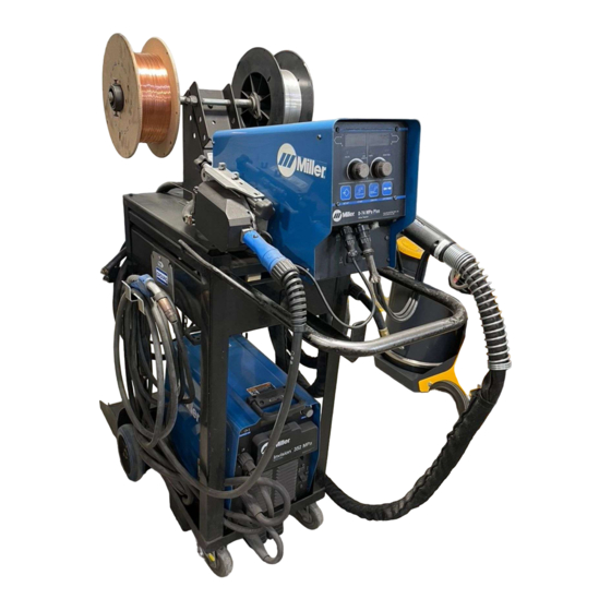
D-74 MPa Plus Swingarc
w/Drives
OM-254063F
2017−06
Processes
MIG (GMAW) Welding
Flux Cored (FCAW) Welding
(Gas-and Self-Shielding)
Submerged (SAW) Welding
Description
Wire Feeder
(Use with CV Power Sources)
8 ft, 12 ft, and 16 ft
File: MIG (GMAW)
Advertisement
Table of Contents
Troubleshooting

Related Manuals for Miller D-74 MPa Plus


Summary of Contents for Miller D-74 MPa Plus
- Page 1 Flux Cored (FCAW) Welding (Gas-and Self-Shielding) Submerged (SAW) Welding Description Wire Feeder (Use with CV Power Sources) D-74 MPa Plus Swingarc w/Drives 8 ft, 12 ft, and 16 ft For product information, Owner’s Manual translations, File: MIG (GMAW) and more, visit...
- Page 2 We know you don’t have time to do it any other way. That’s why when Niels Miller first started building arc welders in 1929, he made sure his products offered long-lasting value and superior quality.
-
Page 3: Table Of Contents
TABLE OF CONTENTS SECTION 1 − SAFETY PRECAUTIONS - READ BEFORE USING ........1-1. -
Page 5: Section 1 − Safety Precautions - Read Before Using
SECTION 1 − SAFETY PRECAUTIONS - READ BEFORE USING som 2015−09 Protect yourself and others from injury — read, follow, and save these important safety precautions and operating instructions. 1-1. Symbol Usage DANGER! − Indicates a hazardous situation which, if Indicates special instructions. - Page 6 D Remove stick electrode from holder or cut off welding wire at FUMES AND GASES can be hazardous. contact tip when not in use. D Wear body protection made from durable, flame−resistant material Welding produces fumes and gases. Breathing (leather, heavy cotton, wool). Body protection includes oil-free these fumes and gases can be hazardous to your clothing such as leather gloves, heavy shirt, cuffless trousers, high health.
-
Page 7: Additional Symbols For Installation, Operation, And Maintenance
1-3. Additional Symbols For Installation, Operation, And Maintenance FIRE OR EXPLOSION hazard. MOVING PARTS can injure. D Do not install or place unit on, over, or near D Keep away from moving parts such as fans. combustible surfaces. D Keep all doors, panels, covers, and guards D Do not install unit near flammables. -
Page 8: California Proposition 65 Warnings
1-4. California Proposition 65 Warnings Welding or cutting equipment produces fumes or gases This product contains chemicals, including lead, known to which contain chemicals known to the State of California to the state of California to cause cancer, birth defects, or other cause birth defects and, in some cases, cancer. -
Page 9: Section 2 − Consignes De Sécurité − Lire Avant Utilisation
SECTION 2 − CONSIGNES DE SÉCURITÉ − LIRE AVANT UTILISATION fre_som_2015−09 Pour écarter les risques de blessure pour vous−même et pour autrui — lire, appliquer et ranger en lieu sûr ces consignes relatives aux précautions de sécurité et au mode opératoire. 2-1. - Page 10 chauffement ou un incendie. Avant de commencer le soudage, vérifier LES PIÈCES CHAUDES peuvent et s’assurer que l’endroit ne présente pas de danger. provoquer des brûlures. D Déplacer toutes les substances inflammables à une distance de D Ne pas toucher à mains nues les parties chaudes. 10,7 m de l’arc de soudage.
-
Page 11: Dangers Supplémentaires En Relation Avec L'installation, Le Fonctionnement Et La Maintenance
D Tenir les bouteilles éloignées des circuits de soudage ou autres LE BRUIT peut endommager l’ouïe. circuits électriques. D Ne jamais placer une torche de soudage sur une bouteille à gaz. Le bruit des processus et des équipements peut affecter l’ouïe. D Une électrode de soudage ne doit jamais entrer en contact avec D Porter des protections approuvées pour les une bouteille. -
Page 12: Proposition Californienne 65 Avertissements
RAYONNEMENT HAUTE LE SOUDAGE À L’ARC risque de FRÉQUENCE (H.F.) risque provoquer des interférences. provoquer des interférences. D L’énergie électromagnétique risque D Le rayonnement haute fréquence (H.F.) peut provoquer des interférences pour l’équipement provoquer des interférences avec les équi- électronique sensible tel que les ordinateurs et l’équipement commandé... -
Page 13: Section 3 − Definitions
SECTION 3 − DEFINITIONS 3-1. Additional Safety Symbols And Definitions Some symbols are found only on CE products. Warning! Watch Out! There are possible hazards as shown by the symbols. Safe1 2012−05 Do not discard product (where applicable) with general waste. Reuse or recycle Waste Electrical and Electronic Equipment (WEEE) by disposing at a designated collection facility. - Page 14 Welding sparks can cause fires. Have a fire extinguisher nearby, and have a watchperson ready to use it. Safe63 2012−06 Do not weld on drums or any closed containers. Safe16 2017−04 Do not remove or paint over (cover) the label. Safe20 2017−04 Drive rolls can injure fingers.
-
Page 15: Miscellaneous Symbols And Definitions
3-2. Miscellaneous Symbols And Definitions Some symbols are found only on CE products. Rated Welding Amperes Three Phase Current Direct Current Primary Voltage (DC) Program Degree Of Protection Output Variable Inductance Hertz Duty Cycle Set Up Preflow Time Input Increase Line Connection Constant Current Process... -
Page 16: Section 4 − Specifications
SECTION 4 − SPECIFICATIONS 4-1. Serial Number And Stock Number Location The serial number and rating information for this product is located on the rear panel. Use rating label to determine input power requirements and/or rated output. For future reference, write serial number in space provided on back cover of this manual. 4-2. -
Page 17: Section 5 − Installation
SECTION 5 − INSTALLATION 5-1. Installing Swivel Into Pipe Post Do not remove Safety Collar until instructed to. Swingpak Base or CBC Cart Pipe Post With Base Steel Bolt Secure as shown using as a mini- mum 1/2 in. diameter SAE grade 5 steel bolts. -
Page 18: Installing Boom And Reel Support
5-3. Installing Boom And Reel Support Swivel Plates Yoke Remove hardware from swivel plates and yoke. Boom Set boom into swivel as shown. Yoke Pin Install pin through yoke. Install cot- ter pin and spread ends. Bolt Install bolt, washers, and nut. Tight- en hardware, and back bolt off one half turn. -
Page 19: Equipment Connection Diagram
5-5. Equipment Connection Diagram Welding Power Source Remote 14 Connection Negative (−) Weld Output Cable Positive (+) Weld Output Cable Workpiece Weld Control (Reference) Boom Swivel 10 Pipe Post And Base 11 Gas Hose 12 Gas Supply and Regulator (Customer Supplied) Shielding gas pressure not to exceed 100 PSI (689 kPa). -
Page 20: Control Box Connections
5-6. Control Box Connections Interconnecting Cables 14 Pin Receptacle Power Connector 19 Pin Receptacle Ref. 252426-C / 252428-D 5-7. 14-Pin Plug Information For Connecting Wire Feeder To Power Source Pin* Pin Information 24 volts AC with respect to socket G. Contact closure to A completes 24 volts AC contactor control circuit. -
Page 21: Removing Safety Collar And Adjusting Boom
5-8. Removing Safety Collar And Adjusting Boom Locking Knob Tighten knob to prevent boom movement. Loosen knob to allow boom movement. Change knob po- sition to limit upward movement. Pull boom down slightly and re- move safety collar. Boom should balance in any position from hori- zontal to 60 degrees above hori- zontal. -
Page 22: Installing Wire Guides And Drive Rolls
5-10. Installing Wire Guides And Drive Rolls Tools Needed: 3/16 in. Open spring shaft carrier. Install inlet guide so groove is centered with When changing wire size or type, screw, and secure guide screw. Drive Roll check drive roll and guide size (see Table 8-1). -
Page 23: Installing Welding Gun
5-12. Installing Welding Gun Gun Locking Tab Power Clamp Knob Gun Connection End Power Pin Groove Installing gun with Accu-Mate connection Loosen power clamp knob to allow power pin of gun to clear the gun locking tab. Push power pin into power clamp as far as possible to align the groove in the power pin of the gun with the gun locking tab. -
Page 24: Installing And Threading Welding Wire
5-13. Installing And Threading Welding Wire Install wire guides and anti-wear guide. Install drive rolls. Pressure Indicator Pressure Scale Adjust Rear Pressure Rolls Adjust Front Rolls No Wire Slip Wire Slips NONCONDUCTIVE NONCONDUCTIVE SURFACE SURFACE Tools Needed: Drive Rolls 3/16, 5/64 in. Back Of Gun 15/16, 3/8 in. -
Page 25: Section 6 − Maintenance & Troubleshooting
SECTION 6 − MAINTENANCE & TROUBLESHOOTING 6-1. Routine Maintenance Maintain more often Disconnect power during severe conditions. before maintaining. 3 Months Clean and Repair or tighten Replace replace weld unreadable cracked terminals. labels. weld cable. Replace Check Check gas Check gun cracked 14-pin cord. -
Page 26: Troubleshooting
6-3. Troubleshooting Disconnect power before troubleshooting. Trouble Remedy Wire feeds, shielding gas flows, but elec- Check interconnecting cord connections. If secure, check cord for continuity and repair or replace (see trode wire is not energized. Sections 5-5 and 5-6). Wire feeder is on, meter(s) do not light Check and reset circuit breaker at welding power source. -
Page 27: Section 7 − Electrical Diagrams
SECTION 7 − ELECTRICAL DIAGRAMS Figure 7-1. Circuit Diagram For Motor/Gas Box 242 330-A Figure 7-2. Circuit Diagram For MPa Plus Motor/Gas Box 250 821-A OM-254063 Page 23... -
Page 28: Section 8 − Parts List
SECTION 8 − PARTS LIST Hardware is common and not available unless listed. 256381-C Figure 8-1. Main Assembly OM-254063 Page 24... - Page 29 Quantity Model Item Dia. Part Mkgs. Description Figure 8-1. Main Assembly ....254864017 . . . Cable, Motor Gas MPa Plus 17Ft (Consisting Of) ..
- Page 30 Hardware is common and not available unless listed. 256382-C Figure 8-2. Boom Assembly OM-254063 Page 26...
- Page 31 Quantity Model Item Part Description Figure 8-2. Boom Assembly (Figure 8-1 Item 11) ... . . 010313 Pin, Cotter Hair .072 X 1.437 ......
- Page 32 See Table 8-1 For Hardware is common and Drive Roll & Wire Guide Kits not available unless listed. Dual Left Dual Right / Single Right Figure 8-3. Drive Assembly, Wire OM-254063 Page 28...
- Page 33 31 32 40 (Left) 62 (Right) 251 255-E OM-254063 Page 29...
- Page 34 Item Dia. Part Description Quantity Mkgs. Figure 8-3. Drive Assembly, Wire ....010668 Screw, Cap Stl Sch .250-20 X 1.500 ....... .
- Page 35 Item Dia. Part Description Quantity Mkgs. Figure 8-3. Drive Assembly, Wire (Continued) ....203423 ..Bushing, Strain Relief .300/.360 Id X .689 Sq Mtg .
- Page 36 Hardware is common and not available unless listed. 081 760-C Figure 8-4. Support, Hub & Reel Item Part Description Quantity Figure 8-4. Support, Hub and Reel (Figure 8-1 Item 10) ..058427 Ring, Retaining Spool .
- Page 37 Table 8-1. Drive Roll And Wire Guide Kits OM-254063 Page 33...
- Page 38 Notes Start Your Professional Over 80,000 trained 400 Trade Square East, Troy, Ohio 45373 Welding Career Now! since 1930! 1-800-332-9448 www.welding.org OM-254063 Page 34...
- Page 39 Effective January 1, 2017 (Equipment with a serial number preface of MH or newer) This limited warranty supersedes all previous Miller warranties and is exclusive with no other guarantees or warranties expressed or implied. Warranty Questions? LIMITED WARRANTY − Subject to the terms and conditions below, 6 Months —...
- Page 40 Contact the Delivering Carrier to: File a claim for loss or damage during shipment. For assistance in filing or settling claims, contact your distributor and/or equipment manufacturer’s Transportation Department. © ORIGINAL INSTRUCTIONS − PRINTED IN USA 2017 Miller Electric Mfg. Co. 2017−01...