Table of Contents
Advertisement
Quick Links
www.ti.com
User's Guide
AM64x/AM243x GP EVM User's Guide
1
Introduction.............................................................................................................................................................................3
1.1 EVM Revisions and Assembly Variants.............................................................................................................................
Notes...........................................................................................................................................................4
2.1 Power-On Usage Note.......................................................................................................................................................
3 System Description................................................................................................................................................................
Features......................................................................................................................................................................6
3.2 Functional Block Diagram..................................................................................................................................................
3.3 Power-On/Off Procedures..................................................................................................................................................
Procedure...................................................................................................................................................9
3.3.2 Power-Off Procedure.................................................................................................................................................
3.4.1 Clocking.....................................................................................................................................................................
3.4.1.1 Ethernet PHY Clock............................................................................................................................................
3.4.1.2 AM64x/AM243x Clock.........................................................................................................................................
3.4.1.3 PCIe Clock..........................................................................................................................................................
3.4.2 Reset.........................................................................................................................................................................
3.4.3 Power........................................................................................................................................................................
Input.........................................................................................................................................................13
3.4.3.2 Reverse Polarity Protection................................................................................................................................
3.4.3.3 Current Monitoring..............................................................................................................................................
Supply......................................................................................................................................................14
Sequencing..............................................................................................................................................16
3.4.3.6 AM64x/AM243x Power.......................................................................................................................................
3.4.4 Configuration.............................................................................................................................................................
Modes.........................................................................................................................................................18
3.4.5
JTAG..........................................................................................................................................................................22
Automation.........................................................................................................................................................25
3.4.7 UART Interfaces........................................................................................................................................................
Interfaces.....................................................................................................................................................29
3.4.8.1 DDR4 Interface...................................................................................................................................................
Interfaces...................................................................................................................................................30
3.4.8.3 OSPI Interface....................................................................................................................................................
3.4.8.5 Board ID EEPROM Interface..............................................................................................................................
3.4.9 Ethernet Interface......................................................................................................................................................
3.4.9.3 Ethernet LED......................................................................................................................................................
Interface......................................................................................................................................................43
Interface.....................................................................................................................................................44
Interface..........................................................................................................................................................44
3.4.13 High Speed Expansion Interface.............................................................................................................................
3.4.14 CAN Interface..........................................................................................................................................................
3.4.15 Interrupt...................................................................................................................................................................
3.4.16 ADC Interface..........................................................................................................................................................
Connector.....................................................................................................................................................56
3.4.18 SPI Interfaces..........................................................................................................................................................
3.4.19 I2C Interfaces..........................................................................................................................................................
3.4.20 FSI Interface............................................................................................................................................................
4 Known Issues and Modifications........................................................................................................................................
4.1 Issue 1 - Embedded XDS110 Connection to AM64x Target in CCS................................................................................
SPRUIX0C - FEBRUARY 2021 - REVISED JUNE 2021
Submit Document Feedback
Table of Contents
Description..................................................................................................................11
Interface.......................................................................................................................................32
Configuration..................................................................................................................35
Configuration..................................................................................................................35
Copyright © 2021 Texas Instruments Incorporated
Table of Contents
AM64x/AM243x GP EVM User's Guide
4
4
5
8
9
10
11
11
11
11
12
13
13
13
17
18
28
29
31
32
33
42
46
54
55
55
56
56
58
59
59
1
Advertisement
Table of Contents

Related Manuals for Texas Instruments AM64 Series


Summary of Contents for Texas Instruments AM64 Series
-
Page 1: Table Of Contents
3.4.20 FSI Interface................................4 Known Issues and Modifications............................4.1 Issue 1 - Embedded XDS110 Connection to AM64x Target in CCS................SPRUIX0C – FEBRUARY 2021 – REVISED JUNE 2021 AM64x/AM243x GP EVM User's Guide Submit Document Feedback Copyright © 2021 Texas Instruments Incorporated... - Page 2 Table 3-17. Test Automation Header (J38) Pin-out........................27 Table 3-18. Board ID Memory Header Information........................Table 3-19. Default Strap Setting of CPSW Ethernet PHY......................AM64x/AM243x GP EVM User's Guide SPRUIX0C – FEBRUARY 2021 – REVISED JUNE 2021 Submit Document Feedback Copyright © 2021 Texas Instruments Incorporated...
-
Page 3: Introduction
Table 4-1. AM64x/AM243x GP EVM Known Issues and Modifications..................Trademarks Sitara ™ and Code Composer Studio ™ , are trademarks of Texas Instruments. ® and Cortex ® are registered trademarks of Arm Limited. All trademarks are the property of their respective owners. -
Page 4: Evm Revisions And Assembly Variants
To avoid high inrush currents and prevent possible damage to the AM64x/AM243x GP EVM components, the proper EVM power on and power off procedures are required. For more details, Section 3.3. AM64x/AM243x GP EVM User's Guide SPRUIX0C – FEBRUARY 2021 – REVISED JUNE 2021 Submit Document Feedback Copyright © 2021 Texas Instruments Incorporated... -
Page 5: System Description
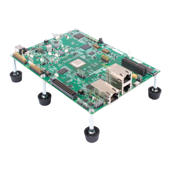
IC and connector component locations. Figure 3-1. Top View of the AM64x/AM243x GP EVM Board SPRUIX0C – FEBRUARY 2021 – REVISED JUNE 2021 AM64x/AM243x GP EVM User's Guide Submit Document Feedback Copyright © 2021 Texas Instruments Incorporated... -
Page 6: Key Features
1 Mbit Inter-Integrated Circuit (I2C) Boot EEPROM I/O Interface: • One CPSW Gigabit Ethernet port and two Industrial Ethernet ports based on the Gigabit Industrial Communication Subsystem (PRU-ICSS-Gb) paired with Texas Instruments Gigabit Ethernet PHY • One USB2.0 interface with Micro AB connector Expansion Bus: •... - Page 7 Status Output: LEDs to indicate power status • INA devices for current monitoring Compliance: • RoHS Compliant • REACH Compliant SPRUIX0C – FEBRUARY 2021 – REVISED JUNE 2021 AM64x/AM243x GP EVM User's Guide Submit Document Feedback Copyright © 2021 Texas Instruments Incorporated...
-
Page 8: Functional Block Diagram
Figure 3-3. General Processor Board Functional Block Diagram Note Diagram is compatible with both the AM6442 MPU and the AM2434 MCU version of the system. AM64x/AM243x GP EVM User's Guide SPRUIX0C – FEBRUARY 2021 – REVISED JUNE 2021 Submit Document Feedback Copyright © 2021 Texas Instruments Incorporated... -
Page 9: Power-On/Off Procedures
2. Place EVM boot switch selectors (SW2, SW3) into selected boot mode. For more details, see Section 3.4.4.1. SPRUIX0C – FEBRUARY 2021 – REVISED JUNE 2021 AM64x/AM243x GP EVM User's Guide Submit Document Feedback Copyright © 2021 Texas Instruments Incorporated... -
Page 10: Power-Off Procedure
1. Switch EVM power switch (SW1) to OFF position. 2. Disconnect AC power from AC/DC converter. 3. Remove DC power plug from EVM power jack (J6). AM64x/AM243x GP EVM User's Guide SPRUIX0C – FEBRUARY 2021 – REVISED JUNE 2021 Submit Document Feedback Copyright © 2021 Texas Instruments Incorporated... -
Page 11: Peripheral And Major Component Description
PCIe reference clock from the SoC (SERDES0_REFCLK0) will be provided to the PCIe slot connector during root complex mode of operation. SPRUIX0C – FEBRUARY 2021 – REVISED JUNE 2021 AM64x/AM243x GP EVM User's Guide Submit Document Feedback Copyright © 2021 Texas Instruments Incorporated... -
Page 12: Reset
AM64x to manually assert reset to the peripheral. Figure 3-5. Overall Reset Architecture of the AM64x/AM243x GP EVM AM64x/AM243x GP EVM User's Guide SPRUIX0C – FEBRUARY 2021 – REVISED JUNE 2021 Submit Document Feedback Copyright © 2021 Texas Instruments Incorporated... -
Page 13: Power
10mΩ ± 0.5% VCC1V8 SoC_DVDD1V8 10mΩ ± 0.5% VDDA1V8 VDDA_1V8 10mΩ ± 0.5% VCC1V2_DDR VDD_DDR4 10mΩ ± 0.5% SPRUIX0C – FEBRUARY 2021 – REVISED JUNE 2021 AM64x/AM243x GP EVM User's Guide Submit Document Feedback Copyright © 2021 Texas Instruments Incorporated... -
Page 14: Power Supply
VDDR_VTT TP48 0.6 V VCC1V8 TP51 1.8 V VPP_1V8 TP52 1.8 V AM243x EVM should be 0.85 V. AM64x/AM243x GP EVM User's Guide SPRUIX0C – FEBRUARY 2021 – REVISED JUNE 2021 Submit Document Feedback Copyright © 2021 Texas Instruments Incorporated... -
Page 15: Figure 3-6. Power Good Leds
VCC_5V0 LD15 VCC3V3_PREREG VCC_3V3_SYS VDD_2V5 VDD_1V1 LD10 VDDA1V8 VDD_CORE VCC_CORE VDD_2V8 LD25 VCC1V2_DDR Figure 3-6. Power Good LEDs SPRUIX0C – FEBRUARY 2021 – REVISED JUNE 2021 AM64x/AM243x GP EVM User's Guide Submit Document Feedback Copyright © 2021 Texas Instruments Incorporated... -
Page 16: Power Sequencing
Power Up and Power Down sequence of all the Power supplies present on the EVM Board. Figure 3-7. Power ON and OFF Sequencing AM64x/AM243x GP EVM User's Guide SPRUIX0C – FEBRUARY 2021 – REVISED JUNE 2021 Submit Document Feedback Copyright © 2021 Texas Instruments Incorporated... -
Page 17: Am64X/Am243X Power
VDD_CORE and VDDR_CORE. In this variant R1 and R3 are installed by default and VDD_CORE supply (U25) is setup for 0.85 V operation. SPRUIX0C – FEBRUARY 2021 – REVISED JUNE 2021 AM64x/AM243x GP EVM User's Guide Submit Document Feedback Copyright © 2021 Texas Instruments Incorporated... -
Page 18: Configuration
For a full description of all AM64x SoC supported bootmodes, see the AM64x Sitara™ Processors Data Manual AM64x Processors Silicon Revision 1.0 Texas Instruments Families of Products Technical Reference Manual. The following boot modes are supported by EVM (and subject to change): 1. -
Page 19: Figure 3-9. Am64X/Am243X Gp Evm Schematic Excerpt, Boot Mode Selection Switches (Sw2, Sw3)
Note The following bit pattern is reversed in the table from the switch order. SPRUIX0C – FEBRUARY 2021 – REVISED JUNE 2021 AM64x/AM243x GP EVM User's Guide Submit Document Feedback Copyright © 2021 Texas Instruments Incorporated... -
Page 20: Table 3-7. Bootmode Bits
RSVD OSPI QSPI RSVD RSVD UART MMC/SD Card eMMC GPMC NAND GPMC NOR PCIe xSPI No-boot / Dev-boot AM64x/AM243x GP EVM User's Guide SPRUIX0C – FEBRUARY 2021 – REVISED JUNE 2021 Submit Document Feedback Copyright © 2021 Texas Instruments Incorporated... -
Page 21: Table 3-10. Primary Boot Media Configuration Bootmode[9:7]
Boot Device RSVD None Mode RSVD RSVD RSVD UART RSVD RSVD Port MMC/SD RSVD RSVD BOOTMODE[14:15] - Reserved SPRUIX0C – FEBRUARY 2021 – REVISED JUNE 2021 AM64x/AM243x GP EVM User's Guide Submit Document Feedback Copyright © 2021 Texas Instruments Incorporated... -
Page 22: Jtag
Pin No. Signal JTAG_CTI_TMS JTAG_CTI_TCK JTAG_TRSTN DGND JTAG_CTI_TDI JTAG_EMU0 JTAG_TDIS JTAG_EMU1 VCC_3V3_SYS JTAG_EMU_RSTN DGND JTAG_TDO SEL_XDS110_INV JTAG_CTI_RTCK DGND DGND AM64x/AM243x GP EVM User's Guide SPRUIX0C – FEBRUARY 2021 – REVISED JUNE 2021 Submit Document Feedback Copyright © 2021 Texas Instruments Incorporated... -
Page 23: Figure 3-11. Jtag Interface
System Description Figure 3-11. JTAG Interface SPRUIX0C – FEBRUARY 2021 – REVISED JUNE 2021 AM64x/AM243x GP EVM User's Guide Submit Document Feedback Copyright © 2021 Texas Instruments Incorporated... -
Page 24: Table 3-15. Ti 60-Pin Connector (J33) Pin-Out
MIPI_TRC_DAT14 MIPI_TRC_DAT19 MIPI_TRC_DAT00 MIPI_TRC_DAT15 MIPI_TRC_DAT20 MIPI_TRC_DAT01 MIPI_TRC_DAT16 MIPI_TRC_DAT21 MIPI_TRC_DAT02 MIPI_TRC_DAT17 MIPI_TRC_DAT22 MIPI_TRC_DAT03 MIPI_TRC_DAT18 MIPI_TRC_DAT23 MIPI_TRC_DAT04 DGND SEL_XDS100_INV MIPI_TRC_DAT05 AM64x/AM243x GP EVM User's Guide SPRUIX0C – FEBRUARY 2021 – REVISED JUNE 2021 Submit Document Feedback Copyright © 2021 Texas Instruments Incorporated... -
Page 25: Test Automation
The other I2C interface is connected to the current measurement and temperature sensing devices present on the I2C1 port of the SoC. The Test Automation connector is used by Texas Instruments for control of software regression testing and comparative power measurements. The connector is provided to allow customers to develop their own testing and power measurements of customer applications. -
Page 26: Figure 3-12. Test Automation Header
System Description www.ti.com Figure 3-12. Test Automation Header AM64x/AM243x GP EVM User's Guide SPRUIX0C – FEBRUARY 2021 – REVISED JUNE 2021 Submit Document Feedback Copyright © 2021 Texas Instruments Incorporated... -
Page 27: Table 3-17. Test Automation Header (J38) Pin-Out
TEST_GPIO4 Input DGND Ground SOC_I2C1_SCL Bidirectional BOOTMODE_I2C_SCL Bidirectional SOC_I2C1_SDA Bidirectional BOOTMODE_I2C_SDA Bidirectional DGND Ground DGND Ground DGND Ground SPRUIX0C – FEBRUARY 2021 – REVISED JUNE 2021 AM64x/AM243x GP EVM User's Guide Submit Document Feedback Copyright © 2021 Texas Instruments Incorporated... -
Page 28: Uart Interfaces
Edit Mode is used to edit the settings of an EEPROM template • Program Mode is used to Program and Erase the device EEPROM(s). Figure 3-13. AM64x/AM243xUART Interfaces AM64x/AM243x GP EVM User's Guide SPRUIX0C – FEBRUARY 2021 – REVISED JUNE 2021 Submit Document Feedback Copyright © 2021 Texas Instruments Incorporated... -
Page 29: Memory Interfaces
(single chip). The placement and routing of the DDR4 device will be point to point with VTT termination. The DDR4 requires 1.2V and thus reduces power demand. Figure 3-14. AM64x/AM243x DDR4 Interface SPRUIX0C – FEBRUARY 2021 – REVISED JUNE 2021 AM64x/AM243x GP EVM User's Guide Submit Document Feedback Copyright © 2021 Texas Instruments Incorporated... -
Page 30: Mmc Interfaces
CAP_VDDSHV_SDLDO pin. CAP_VDDSHV_SDLDO is connected to both the IO voltage of SD signals and VDDSHV_MMC1 power pins of the SoC. Figure 3-15. Micro SD Interface AM64x/AM243x GP EVM User's Guide SPRUIX0C – FEBRUARY 2021 – REVISED JUNE 2021 Submit Document Feedback Copyright © 2021 Texas Instruments Incorporated... -
Page 31: Ospi Interface
Remove 0E resistors from the following 1. OSPI_DQ4 to OSPI_DQ7 nets (R432, R441, R442, R443) 2. OSPI_INTn (R158) SPRUIX0C – FEBRUARY 2021 – REVISED JUNE 2021 AM64x/AM243x GP EVM User's Guide Submit Document Feedback Copyright © 2021 Texas Instruments Incorporated... -
Page 32: Spi Eeprom Interface
First software release number VendorID Build_Week Week of the year of production Build_Year Year of production BoardID Serial_Nbr Incrementing board number AM64x/AM243x GP EVM User's Guide SPRUIX0C – FEBRUARY 2021 – REVISED JUNE 2021 Submit Document Feedback Copyright © 2021 Texas Instruments Incorporated... -
Page 33: Ethernet Interface
The objective of the PHY used to connect this port is that the PHY should support both RGMII and MII modes, hence DP83869 (48 pin) PHY is selected. SPRUIX0C – FEBRUARY 2021 – REVISED JUNE 2021 AM64x/AM243x GP EVM User's Guide Submit Document Feedback Copyright © 2021 Texas Instruments Incorporated... -
Page 34: Figure 3-19. Ethernet Interface - Icssg Domain
CPSW_RGMII1 used for the first PHY). Hence the same DP83869 (48pin) PHY is used for this port as well. Figure 3-19. Ethernet Interface - ICSSG Domain AM64x/AM243x GP EVM User's Guide SPRUIX0C – FEBRUARY 2021 – REVISED JUNE 2021 Submit Document Feedback Copyright © 2021 Texas Instruments Incorporated... -
Page 35: Dp83867 Phy Default Configuration
01111 (0Fh) using the strap resistors. Footprint for both pull up and pull down is provided on all the strapping pins. SPRUIX0C – FEBRUARY 2021 – REVISED JUNE 2021 AM64x/AM243x GP EVM User's Guide Submit Document Feedback Copyright © 2021 Texas Instruments Incorporated... -
Page 36: Table 3-19. Default Strap Setting Of Cpsw Ethernet Phy
LEDs for different modes of operation. The LED operation mode can be selected using AM64x/AM243x GP EVM User's Guide SPRUIX0C – FEBRUARY 2021 – REVISED JUNE 2021 Submit Document Feedback Copyright © 2021 Texas Instruments Incorporated... - Page 37 LEDCR1 register address 0x0018 on the DP83867 device and LEDS_CFG1 register address 0x0018 on the DP83869 device. The default configuration are as follows. SPRUIX0C – FEBRUARY 2021 – REVISED JUNE 2021 AM64x/AM243x GP EVM User's Guide Submit Document Feedback Copyright © 2021 Texas Instruments Incorporated...
- Page 38 LED1 is connected to RJ45 LED (Green) to indicate 1000 MHz speed LED2 is connected to RJ45 LED (Yellow) to indicate transmit/receive activity. AM64x/AM243x GP EVM User's Guide SPRUIX0C – FEBRUARY 2021 – REVISED JUNE 2021 Submit Document Feedback Copyright © 2021 Texas Instruments Incorporated...
-
Page 39: Figure 3-20. Am64X/Am243Xethernet Interfaces - Cpsw Ethernet Strap Settings
System Description Figure 3-20. AM64x/AM243xEthernet Interfaces - CPSW Ethernet Strap Settings SPRUIX0C – FEBRUARY 2021 – REVISED JUNE 2021 AM64x/AM243x GP EVM User's Guide Submit Document Feedback Copyright © 2021 Texas Instruments Incorporated... -
Page 40: Figure 3-21. Am64X/Am243X Ethernet Interfaces - Icssg1 Ethernet Strap Settings
System Description www.ti.com Figure 3-21. AM64x/AM243x Ethernet Interfaces - ICSSG1 Ethernet Strap Settings AM64x/AM243x GP EVM User's Guide SPRUIX0C – FEBRUARY 2021 – REVISED JUNE 2021 Submit Document Feedback Copyright © 2021 Texas Instruments Incorporated... -
Page 41: Figure 3-22. Am64X/Am243X Ethernet Interfaces - Icssg2 Ethernet Strap Settings
Figure 3-22. AM64x/AM243x Ethernet Interfaces - ICSSG2 Ethernet Strap Settings Note Resistors that are highlighted by red color box are DNI components. SPRUIX0C – FEBRUARY 2021 – REVISED JUNE 2021 AM64x/AM243x GP EVM User's Guide Submit Document Feedback Copyright © 2021 Texas Instruments Incorporated... -
Page 42: Ethernet Led
These eight LED can be toggled based on the user application. Figure 3-23. AM64x/AM243x GP EVM Ethernet Interface LED AM64x/AM243x GP EVM User's Guide SPRUIX0C – FEBRUARY 2021 – REVISED JUNE 2021 Submit Document Feedback Copyright © 2021 Texas Instruments Incorporated... -
Page 43: Display Interface
FPC connector on the EVM having part number 10051922-1410ELF from Amphenol ICC and the pin details are mentioned in Table 3-21. Table 3-21. Display Connector (J36) Pin-Out Pin No. Signal VDDB RES# IREF VCOMH SPRUIX0C – FEBRUARY 2021 – REVISED JUNE 2021 AM64x/AM243x GP EVM User's Guide Submit Document Feedback Copyright © 2021 Texas Instruments Incorporated... -
Page 44: Usb 2.0 Interface
MCU_PORz pin. The reset signal is connected to 3 pin header and the selection should be made with a jumper. The PCIe x4 Connector JTAG signals are unused and test points are provided on the signals. AM64x/AM243x GP EVM User's Guide SPRUIX0C – FEBRUARY 2021 – REVISED JUNE 2021 Submit Document Feedback Copyright © 2021 Texas Instruments Incorporated... -
Page 45: Figure 3-25. Am64X/Am243X Pcie Interface
GROUND REFCLK- SERDER_REFCLK0N PETp0 SERDES_TXP0 GROUND PETn0 SERDES_TXN0 PERp0 SERDES_RXP0 PERn0 SERDES_RXN0 PRSNT2#_1 J35.2 GROUND GROUND RSVD1 PETp1 SPRUIX0C – FEBRUARY 2021 – REVISED JUNE 2021 AM64x/AM243x GP EVM User's Guide Submit Document Feedback Copyright © 2021 Texas Instruments Incorporated... -
Page 46: High Speed Expansion Interface
For a full list of available secondary multiplexing of signal functions implemented in device subsystems, see the EVM Schematic, Sysconfig Tool and device-specific data sheet. AM64x/AM243x GP EVM User's Guide SPRUIX0C – FEBRUARY 2021 – REVISED JUNE 2021 Submit Document Feedback Copyright © 2021 Texas Instruments Incorporated... -
Page 47: Table 3-24. Selection Of Prg0 Signals On Application Connector
FSI_RX0_CLK , UART2_CTSn, EHRPWM2_A, TRC_DATA6, GPIO0_23, PRG0_PWM2_A2, BOOTMODE08 DGND DGND DGND VCC3V3_IO_HSE VCC3V3_IO_HSE VCC3V3_IO_HSE SOC_SPI1_CLK EHRPWM6_SYNCI, GPIO1_49 VCC1V8_HSE VCC1V8_HSE DGND SPRUIX0C – FEBRUARY 2021 – REVISED JUNE 2021 AM64x/AM243x GP EVM User's Guide Submit Document Feedback Copyright © 2021 Texas Instruments Incorporated... - Page 48 RGMII1_RD3, RMII1_TXD1, GPIO1_37, PRG0_ECAP0_SYNC_OUT, PRG0_ECAP0_SYNC_IN HSE_MCAN1_RX/I2C3_SDA ECAP2_IN_APWM_OUT, OBSCLK0, TIMER_IO5, UART5_TXD, EHRPWM_SOCB, GPIO1_63, EQEP2_B, UART0_DSRn DGND SOC_I2C0_SCL UART6_CTS, GPIO1_64 AM64x/AM243x GP EVM User's Guide SPRUIX0C – FEBRUARY 2021 – REVISED JUNE 2021 Submit Document Feedback Copyright © 2021 Texas Instruments Incorporated...
- Page 49 CP_GEMAC_CPTS0_TS_COMP, EHRPWM8_B, GPIO1_19, UART4_RTSn, GPMC0_A6, UART3_RXD PRG0_PRU0GPO0 PRG0_PRU0_GPI0, PRG0_RGMII1_RD0, PRG0_PWM3_A0, GPIO1_0, UART2_CTSn PRG0_PRU1GPO4 PRG0_PRU1_GPI4, PRG0_RGMII2_RX_CTL, PRG0_PWM2_B2, GPIO1_24, EQEP1_B, UART6_TXD SPRUIX0C – FEBRUARY 2021 – REVISED JUNE 2021 AM64x/AM243x GP EVM User's Guide Submit Document Feedback Copyright © 2021 Texas Instruments Incorporated...
- Page 50 PRG0_PWM2_A2, GPIO1_22, EQEP0_S, UART5_RTSn DGND PRG0_PRU1GPO11 PRG0_PRU1_GPI11, PRG0_RGMII2_TD0, GPIO1_31, EQEP2_I, UART4_RXD PRG0_PRU0GPO15 PRG0_PRU0_GPI15, PRG0_RGMII1_TX_CTL, PRG0_PWM0_B1, SPI3_CS1, GPIO1_15, GPMC0_A16 DGND AM64x/AM243x GP EVM User's Guide SPRUIX0C – FEBRUARY 2021 – REVISED JUNE 2021 Submit Document Feedback Copyright © 2021 Texas Instruments Incorporated...
- Page 51 BOOTMODE11 DGND HSE_PRG0_PRU1_GPO9 PRG0_PRU1_GPI9, PRG0_UART0_RXD, RGMII1_RD1, PRG0_IEP0_EDIO_DATA_IN_OUT30, GPIO1_29, EQEP0_I, UART5_RXD HSE_MCAN0_RX/UART4_TXD UART4_TXD, TIMER_IO3, SYNC3_OUT, SPI4_CS2, GPIO1_61, EQEP2_S, UART0_RIn SPRUIX0C – FEBRUARY 2021 – REVISED JUNE 2021 AM64x/AM243x GP EVM User's Guide Submit Document Feedback Copyright © 2021 Texas Instruments Incorporated...
-
Page 52: Figure 3-26. Am64X/Am243X High Speed Expansion Connector
PRG0_PRU1_GPI10, PRG0_UART0_TXD, PRG0_PWM2_TZ_IN, RGMII1_RD2, RMII1_TXD0, PRG0_IEP0_EDIO_DATA_IN_OUT31, GPIO1_30, EQEP1_I, UART6_RXD DGND DGND MCU_PORZ Figure 3-26. AM64x/AM243x High Speed Expansion Connector AM64x/AM243x GP EVM User's Guide SPRUIX0C – FEBRUARY 2021 – REVISED JUNE 2021 Submit Document Feedback Copyright © 2021 Texas Instruments Incorporated... -
Page 53: Figure 3-27. Am64X/Am243X High Speed Expansion Connector - Part 1
System Description Figure 3-27. AM64x/AM243x High Speed Expansion Connector - Part 1 SPRUIX0C – FEBRUARY 2021 – REVISED JUNE 2021 AM64x/AM243x GP EVM User's Guide Submit Document Feedback Copyright © 2021 Texas Instruments Incorporated... -
Page 54: Can Interface
Table 3-25. CAN (J31 and J32) Pin-out CAN0 J31 CAN1 J32 Pin No. Signal Pin No. Signal MCAN0_H MCAN0_H MCAN0_L MCAN0_L AM64x/AM243x GP EVM User's Guide SPRUIX0C – FEBRUARY 2021 – REVISED JUNE 2021 Submit Document Feedback Copyright © 2021 Texas Instruments Incorporated... -
Page 55: Interrupt
DGND ADC0_AIN7 DGND ADC0_AIN6 DGND VDDA_ADC ADC0_AIN1 DGND ADC0_AIN0 ADC0_AIN2 DGND ADC0_AIN5 VDDA_ADC DGND ADC0_AIN3 DGND ADC0_AIN4 DGND SPRUIX0C – FEBRUARY 2021 – REVISED JUNE 2021 AM64x/AM243x GP EVM User's Guide Submit Document Feedback Copyright © 2021 Texas Instruments Incorporated... -
Page 56: Safety Connector
J5 for AM64x/AM243x processor slave operation. Pin outs of I2C test header is given in Table 3-28. Table 3-28. I2C Test Header (J5) Pin-out Pin No. Signal DGND SoC_I2C0_SDA SoC_I2C0_SCL AM64x/AM243x GP EVM User's Guide SPRUIX0C – FEBRUARY 2021 – REVISED JUNE 2021 Submit Document Feedback Copyright © 2021 Texas Instruments Incorporated... -
Page 57: Figure 3-30. Am64X/Am243X I2C Interfaces And Address Assignment Of Peripherals
5. MCU_I2C1: This is connected to the safety connector. Figure 3-30 depicts the I2C tree. Figure 3-30. AM64x/AM243x I2C Interfaces and Address Assignment of Peripherals SPRUIX0C – FEBRUARY 2021 – REVISED JUNE 2021 AM64x/AM243x GP EVM User's Guide Submit Document Feedback Copyright © 2021 Texas Instruments Incorporated... -
Page 58: Fsi Interface
Pin No. Signal FSI_TX0_CLK FSI_RX0_CLK DGND DGND FSI_TX0_D0 FSI_RX0_D0 FSI_TX0_D1 FSI_RX0_D1 DGND VCC_3V3_SYS Figure 3-31. AM64x/AM243x FSI Interface AM64x/AM243x GP EVM User's Guide SPRUIX0C – FEBRUARY 2021 – REVISED JUNE 2021 Submit Document Feedback Copyright © 2021 Texas Instruments Incorporated... -
Page 59: Known Issues And Modifications
2. EVM power is enabled and the AM64x is brought up in no-boot mode. 3. In CCS, an initial CCS target connection to the M3 DMSC core is then attempted. SPRUIX0C – FEBRUARY 2021 – REVISED JUNE 2021 AM64x/AM243x GP EVM User's Guide Submit Document Feedback Copyright © 2021 Texas Instruments Incorporated... -
Page 60: Figure 4-2. Xds110 Ccs Connection Error Dialog
PC. A similar tool is available under the Linux OS install of CCS. Figure 4-3. XDS110 debug reset utility command-line function AM64x/AM243x GP EVM User's Guide SPRUIX0C – FEBRUARY 2021 – REVISED JUNE 2021 Submit Document Feedback Copyright © 2021 Texas Instruments Incorporated... - Page 61 • AM64x Sitara™ Processors Data Manual • AM64x Processors Silicon Revision 1.0 Texas Instruments Families of Products Technical Reference Manual 6 Revision History NOTE: Page numbers for previous revisions may differ from page numbers in the current version. Changes from Revision B (March 2021) to Revision C (June 2021) Page •...
- Page 62 TI products. TI’s provision of these resources does not expand or otherwise alter TI’s applicable warranties or warranty disclaimers for TI products.IMPORTANT NOTICE Mailing Address: Texas Instruments, Post Office Box 655303, Dallas, Texas 75265 Copyright © 2021, Texas Instruments Incorporated...