Table of Contents
Advertisement
Quick Links
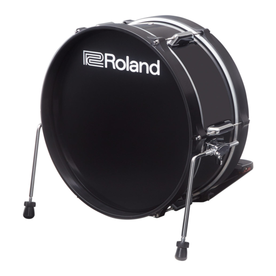
KD-180L
Check the Included Items
After opening the package, check that all of the included items
are present. If anything is missing, contact your dealer.
Main unit
Rod (with memory lock) × 2
Connection cable
Drum key
Owner's Manual
* This package does not include a kick pedal or beater. A variety of
commercially available beaters can be used, including felt, plastic, or
wood types. However, if you use a felt beater, strike marks of the felt
might remain on the striking surface.
Descriptions
Shell
Hoop
Bracket
Front head
Rod lock
knob
Rod
Foot nut
Foot
Tension bolt
Batter head's strike surface
Batter hoop
Batter head
TRIGGER OUT jack
© 2020 Roland Corporation
*
5
1
0
0
0
7
0
2
0
2
-
0
1
*
Assembling the KD-180L
NOTE
During assembly, take care that the weight of the bass drum does not
pinch your hand or foot.
1.
Loosen the rod lock knob, and attach the rod.
Position the rod so that the memory lock is in close
contact with the bracket of the main unit, and then
tighten the rod lock knob.
* We recommend that you use the memory lock in the factory-set
position. This allows installation at the recommended rod length
and angle.
Memory lock
Rod lock
knob
Rod
2.
Adjust the tip of the rods (spike/rubber)
appropriately for the surface on which you're
placing the KD-180L.
Soft floor
Spike
Carpet, etc.
Hard floor
Rubber
Wood flooring, concrete, etc.
If you loosen the foot nut and rotate the foot to raise it,
the spike will be exposed.
Tighten the foot nut to secure the position of the foot.
Spike
Rubber
Foot nut
Foot
Spike
* The tip of the spike is sharp; handle it with care.
* Using the spike leg tips on wood flooring may damage the floor; the
rubber leg tips should be used on wood flooring.
3.
Attach the kick pedal at the kick pedal
attachment position (the gap in the batter
hoop).
Adjust the location at which the kick pedal is attached
so that the beater strikes the center of the batter head's
strike surface; then securely fasten the kick pedal to the
KD-180L.
* Take care not to pinch your fingers.
Beater must hit the center
of the striking surface
Attach to the gap in
the batter hoop
Owner's Manual
English
Attach the kick pedal so
that its entire bottom
surface contacts the floor.
MEMO
If the kick pedal installation is not stable, or if you want to change the
strike feel, adjust the rod length or angle.
You can also adjust the length and angle of the rod by using a drum key to
adjust the memory lock.
Memory lock
Using Double Kick Pedals
The KD-180L can also be used with double kick pedals.
Adjust the striking points of the two beaters so that they are at
equal distances to the left and right of the batter head's strike
surface.
Correct
Incorrect
If the beater's striking point cannot be aligned appropriately
Depending on the kick pedal, it might not be possible to attach
it to the bass drum so that the strike point of the two beaters is
located symmetrically to the left and right of the center of the
batter head's strike surface.
In this case, use the following procedure to adjust the position of
the batter head's strike surface.
1.
Remove the tension bolts and the batter hoop.
Tension bolt
Batter hoop
Batter head
NOTE
To avoid injury, damage, or malfunction, do not detach the batter
head from the shell. Take care not to injure your hands or feet while
working.
Before using this unit, carefully read the leaflet "USING THE UNIT SAFELY" and "IMPORTANT NOTES. " After reading, keep the
document(s) where it will be available for immediate reference.
2.
Turn the batter head to approximately the
position shown in the illustration.
Batter head
(approximate)
NOTE
To avoid damaging the interior, take care not to turn the batter head
excessively (guideline for turning: ±30 degrees).
3.
Place the batter hoop back.
4.
Working alternately across opposite sides of the
drum, lightly tighten each tension bolt until the
batter hoop do not wobble.
4
6
Tension bolt
2
1
5
3
5.
Then tighten each tension bolt another 1/4 of a
turn to secure the batter head.
* If the tension of the batter head is excessive or insufficient, the
sensor might malfunction, or the impact might be louder.
Connecting to the Drum Sound Module
Connect the KD-180L to your drum sound module.
Use the included connection cable to make the connection.
Connect the "L" plug of the connection cable to the jack of the
KD-180L.
(Example) TD-17
"I"
plug
"L" plug
Recommended Parameter Settings
These are the recommended values for the trigger parameters
when using the KD-180L with various drum sound modules.
If the "PAD TYPE" or "TRIG TYPE" of your drum sound module
provides a "KD180L" setting, choose "KD180L. " If "KD180L" is not
one of the available values, refer to the support information on
the Roland website.
http://roland.cm/trigger_prm
You may need to adjust the trigger parameters depending on
how you've mounted the KD-180L and the location at which
you've installed it.
For details on editing refer to the owner's manual of your drum
sound module.
Adjusting the Head Tension
Adjust the tension of the batter head before you play the KD-180L.
You can vary the strike response (playing feel) by adjusting the
tension.
1.
Adjust each tension bolt little by little, working
back and forth across the head in the order
shown in the illustration.
4
6
Tension bolt
2
1
5
3
* Fully tightening a tension bolt at only a single location will produce
uneven tensioning, which will make it impossible to achieve correct
strike response and may also cause malfunctions.
2.
Adjust each tension bolt so that the head is
tensioned evenly.
Main Specifications
Roland KD-180L: Bass drum
18 (Diameter) x 7 (Depth) inches
Shell
Wood shell
Trigger
1 (Head)
Acceptable
Single pedal, Twin pedal
pedal
Connector
TRIGGER OUT jack
502 (W) x 240 (D) x 478 (H) mm
Dimensions
19-13/16 x 9-1/2 x 18-7/8 inches
* Excluding legs
5.6 kg
Weight
12 lbs 6 oz
* This document explains the specifications of the product at the time
that the document was issued. For the latest information, refer to the
Roland website.
Advertisement
Table of Contents

Related Manuals for Roland KD-180L


Summary of Contents for Roland KD-180L
- Page 1 NOTE After opening the package, check that all of the included items Adjust the tension of the batter head before you play the KD-180L. Attach the kick pedal so Batter head are present. If anything is missing, contact your dealer.
- Page 2 Tuning bolt 2.0 kg 2.3 kg 1.9 kg Weight When you need repair service, access this URL and find your nearest Roland Service Center or authorized 4 lbs 7 oz 5 lbs 2 oz 4 lbs 4 oz Loosen your country.
- Page 3 When you need repair service, access this URL and find your nearest Roland Service Center or authorized Roland distributor in your country. http://roland.cm/service...
- Page 4 CY-13R V-CYMBAL RIDE CY-12C V-CYMBAL CRASH Owner’s Manual Before using this unit, carefully read the sections entitled: “USING THE UNIT SAFELY” and “IMPORTANT NOTES” (p. 2; p. 3). These sections provide important information concerning the proper operation of the unit. Additionally, in order to feel assured that you have gained a good grasp of every feature provided by your new unit, Owner’s manual should be read in its entirety.
-
Page 5: Using The Unit Safely
(except when this manual provides specific instructions directing you to do so). Refer all servicing • In households with small to your retailer, the nearest Roland children, an adult should provide supervision until the Service Center, or an authorized Roland distributor, as listed on the “Information”... -
Page 6: Important Notes
6 Roland,V-Drums, and V-CYMBALS are registered trademarks of that has been slightly dampened with water. To remove stubborn Roland Corporation in the United States and/or other countries. dirt, use a cloth impregnated with a mild, non-abrasive detergent. Afterwards, be sure to wipe the unit thoroughly with a soft, dry cloth. -
Page 7: Getting Started
* The CY-13R is not capable of detecting the striking position. Weight 940 g / 2 lbs 2 oz If you’re using a Roland percussion sound module that is capable Owner’s manual, Wing nut, Felt washer, of detecting the striking position, you’ll need to set the ride’s Position Ctrl to OFF. -
Page 8: Making The Settings
OUTPUT jack the performer’s perspective. Attach the V-Cymbal, while positioning it BOW/EDGE BOW/EDGE so the Roland logo is located on the side OUTPUT jack OUTPUT jack opposite the performer. RD cable CR1, 2 cable (TD-9, TD-4) (TD-9, TD-4) -
Page 9: Playing Methods
If you choke an area where there is no sensor, the Edge sensor sound does not stop. Roland logo Edge sensor * On the CY-13R, edge shots are possible when the connection is made to the BOW/EDGE OUTPUT jack. - Page 10 Trigger Parameter Settings for the Percussion Sound Module Recommended Settings for the Trigger Parameters These are the recommended trigger parameter settings when using the V-Cymbal with various models of sound module. You may need to adjust the trigger parameters depending on how you’ve attached the V-Cymbal and the location at which you’ve installed it.
- Page 11 For EU Countries 有关产品中所含有害物质的说明 本资料就本公司产品中所含的特定有害物质及其安全性予以说明。 本资料适用于����年�月� 日以后本公司所制造的产品。 环保使用期限 此标志适用于在中国国内销售的电子信息产品, 表示环保使用期限的年数。 所谓环保使用 期限是指在自制造日起的规定期限内, 产品中所含的有害物质不致引起环境污染, 不会对 人身、 财产造成严重的不良影响。 环保使用期限仅在遵照产品使用说明书, 正确使用产品的条件下才有效。 不当的使用, 将会导致有害物质泄漏的危险。 产品中有害物质的名称及含量 有害物质 部件名称 六价铬 多溴联苯 多溴二苯醚 铅 (Pb) 汞 (Hg) 镉 (Cd) (Cr ( VI) ) (PBB) (PBDE) 外壳 (壳体) 电子部件...
- Page 12 Importer: Roland Corporation ENA 23 Zone 1 nr. 1620 Klaus-Michael Kuehnelaan 13, 2440 Geel, BELGIUM When you need repair service, access this URL and nd your nearest Roland Service Center or authorized Roland dis For the U.K. your country. Manufacturer:...