Pilz PZE X4VP Operating Manual
Safety relays
Hide thumbs
Also See for PZE X4VP:
- Operating manual (27 pages) ,
- Operating instructions manual (16 pages) ,
- Operating instructions manual (16 pages)
Table of Contents
Advertisement
Quick Links
Advertisement
Table of Contents

Related Manuals for Pilz PZE X4VP


Summary of Contents for Pilz PZE X4VP
- Page 1 PZE X4VP Safety relays Operating Manual1003202EN08...
- Page 2 Preface This document is a translation of the original document. All rights to this documentation are reserved by Pilz GmbH & Co. KG. Copies may be made for internal purposes. Suggestions and comments for improving this documentation will be gratefully received. Pilz®, PIT®, PMI®, PNOZ®, Primo®, PSEN®, PSS®, PVIS®, SafetyBUS p®, SafetyEYE®, SafetyNET p®, the spirit of safety® are registered and protected trademarks of Pilz GmbH & Co. KG in some countries. SD means Secure Digital...
-
Page 3: Table Of Contents
Content Introduction Validity of documentation Retaining the documentation Definition of symbols Intended use For your safety Unit features Safety features Block diagram/terminal configuration Function description Installation Wiring Preparing for operation Operation Status indicators Faults – Interference Dimensions in mm Technical details Safety characteristic data Supplementary data Service life graph Remove plugin terminals Order reference EC declaration of conformity Operating Manual PZE X4VP 1003202EN08... -
Page 4: Introduction
PZE X4VP Introduction Validity of documentation This documentation is valid for the product PZE X4VP. It is valid until new documentation is published. This operating manual explains the function and operation, describes the installation and provides guidelines on how to connect the product. Retaining the documentation This documentation is intended for instruction and should be retained for future reference. Definition of symbols Information that is particularly important is identified as follows: DANGER! This warning must be heeded! It warns of a hazardous situation that poses an immediate threat of serious injury and death and indicates preventive measures that can be taken. WARNING! This warning must be heeded! It warns of a hazardous situation that could lead to serious injury and death and indicates preventive measures that can be taken. CAUTION! This refers to a hazard that can lead to a less serious or minor injury plus material damage, and also provides information on preventive measures that can be taken. NOTICE This describes a situation in which the product or devices could be dam aged and also provides information on preventive measures that can be taken. It also highlights areas within the text that are of particular import ance. Operating Manual PZE X4VP 1003202EN08... -
Page 5: Intended Use
PZE X4VP INFORMATION This gives advice on applications and provides information on special fea tures. Intended use The unit meets the requirements of EN 6094751, EN 602041 and VDE 01131. The con tact expansion module is used to increase the number of instantaneous safety contacts available on a base unit. Base units are all safety relays with feedback loop monitoring. The category that can be achieved in accordance with EN ISO 138491 depends on the category of the base unit. The contact expansion module may not exceed this. The delayon deenergisation safety contacts may only be used up to max. PL d (Cat. 3). For your safety Only install and commission the unit if you have read and understood these operating instructions and are familiar with the applicable regulations for health and safety at work and accident prevention. Ensure VDE and local regulations are met, especially those relating to safety. Any guarantee is rendered invalid if the housing is opened or unauthorised modifica tions are carried out. Note for overvoltage category III: If voltages higher than low voltage (>50 VAC or >120 VDC) are present on the unit, connected control elements and sensors must have a rated insulation voltage of at least 250 V. Unit features Positiveguided relay outputs: – 4 safety contacts (N/O), delayon deenergisation LED display for: – Switch status channel 1/2 Connection for feedback loop Operation: singlechannel Unit types with various delay times Plugin connection terminals (either springloaded terminal or screw terminal) See order reference for unit types Safety features The unit meets the following safety requirements: The contact expander module expands an existing circuit. As the output relays are monitored via the base unit's feedback loop, the safety functions on the existing circuit are transferred to the contact expander module. The safety function remains effective in the case of a component failure. Operating Manual PZE X4VP 1003202EN08... -
Page 6: Block Diagram/Terminal Configuration
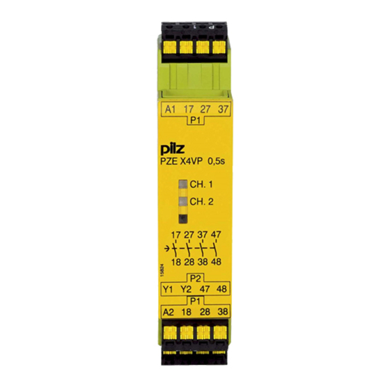
PZE X4VP Earth fault in the feedback loop: Detected, depending on the base unit that is used. Earth fault in the input circuit: The output relays deenergise and the safety contacts open. Block diagram/terminal configuration A1 A2 17 27 37 Input PNOZ X4VP 3s PZE X4VP CH.1 CH.2 Power Y1 Y2 47 18 28 38 *Insulation between the nonmarked area and the relay contacts: Basic insulation (over voltage category III), Protective separation (overvoltage category II) Function description The contact expansion module is an addon device with delayon deenergisation, and it is used to expand a safety circuit. The contact expansion module is driven by a base unit (e. g. emergency stop relay). Functional procedure after closing the safety contacts of the base unit: – The supply voltage is present at the input (A1) of the contact expansion module. – Close the safety contacts 1718, 2728, 3738 and 4748. – The LEDs "CH. 1" and "CH. 2" are lit. Functional procedure after opening the safety contacts of the base unit: –... -
Page 7: Wiring
PZE X4VP If more than 2 units are installed next to each other in the control cabinet, leave a dis tance of at least 6 mm between the units. Wiring Please note: Information given in the "Technical details [ 9]" must be followed. Outputs 1718, 2728, 3738 and 4748 are delayon deenergisation safety contacts. To prevent contact welding, a fuse should be connected before the output contacts (see Technical details). Calculation of the max. cable runs l in the input circuit: max lmax / km = max. overall cable resistance (see Technical details) lmax / km = cable resistance/km Use copper wire that can withstand 60/75 °C. Sufficient fuse protection must be provided on all output contacts with capacitive and in ductive loads. Do not switch low currents using contacts that have been used previously with high cur rents. Preparing for operation Supply voltage 24 V DC Input circuit Singlechannel Dualchannel Base unit: 24 V DC Safety relay PNOZ X Driven via safety contacts Base unit: Safety relay PNOZmulti Driven via semiconductor outputs (24 VDC) Operating Manual PZE X4VP... -
Page 8: Operation
PZE X4VP Feedback loop Base unit: Safety relay PNOZ X Base unit: Safety relay PNOZmulti Y1, Y2 and Input are inputs on the base unit; they evaluate the feedback loop Operation Status indicators CH.1 Safety contacts of channel 1 are closed. CH.2 Safety contacts of channel 2 are closed. Faults – Interference By closing or interrupting the input circuit you can check whether the unit switches on or off correctly. For safety reasons, the unit cannot be started if the following faults are present: Contact malfunction: As the contact block is connected to a base unit, reactivation will not be possible if the contacts have welded after the input circuit has opened. Open circuit, short circuit or earth fault ( e.g. in the input circuit) In the case of an error, the delayon deenergisation safety contacts may open before the delay time has elapsed. Dimensions in mm * with springloaded terminals 22,5 94 (3.70") (0.88") * 101 (3.98") Operating Manual PZE X4VP 1003202EN08... -
Page 9: Technical Details
PZE X4VP Technical details Order no. 777580 – 777583 See below for more order numbers General 777580 777581 777582 777583 CCC, CE, GOST, CCC, CE, GOST, CCC, CE, GOST, CCC, CE, GOST, Approvals TÜV, cULus Listed TÜV, cULus Listed TÜV, cULus Listed TÜV, cULus Listed Electrical data 777580 777581 777582 777583 Supply voltage Voltage 24 V 24 V 24 V 24 V Kind Voltage tolerance 15 %/+10 % 15 %/+10 % 15 %/+10 % 15 %/+10 % Output of external power supply (DC) 2,5 W 2,5 W 2,5 W 2,5 W Residual ripple... - Page 10 PZE X4VP Relay outputs 777580 777581 777582 777583 Utilisation category In accordance with the standard EN 6094741 EN 6094741 EN 6094741 EN 6094741 Safetycontacts, delayed, AC1 at 240 V 240 V 240 V 240 V Min. current 0,01 A 0,01 A 0,01 A 0,01 A Max. current 6,0 A 6,0 A 6,0 A 6,0 A Max. power 1500 VA 1500 VA 1500 VA 1500 VA Safetycontacts, delayed, DC1 at 24 V 24 V 24 V 24 V Min. current 0,01 A 0,01 A...
- Page 11 PZE X4VP Relay outputs 777580 777581 777582 777583 Contact fuse protec tion external, delayed safety con tacts Max. melting in tegral 66 A²s 66 A²s 66 A²s 66 A²s Blowout fuse, quick 6 A 6 A 6 A 6 A Blowout fuse, slow 4 A 4 A 4 A 4 A Blowout fuse gG 6 A 6 A 6 A 6 A Circuit breaker, 24 V AC/DC, characteristic B/C 4 A 4 A 4 A 4 A AgCuNi + 0,2 µm AgCuNi + 0,2 µm AgCuNi + 0,2 µm...
- Page 12 PZE X4VP Environmental data 777580 777581 777582 777583 Vibration In accordance with the standard EN 6006826 EN 6006826 EN 6006826 EN 6006826 Frequency 10,0 55,0 Hz 10,0 55,0 Hz 10,0 55,0 Hz 10,0 55,0 Hz Amplitude 0,35 mm 0,35 mm 0,35 mm 0,35 mm Airgap creepage In accordance with the standard EN 609471 EN 609471 EN 609471 EN 609471 Overvoltage cat egory III / II III / II III / II III / II Pollution degree Rated insulation voltage 250 V 250 V 250 V 250 V...
- Page 13 PZE X4VP Mechanical data 777580 777581 777582 777583 Dimensions Height 94,0 mm 94,0 mm 94,0 mm 94,0 mm Width 22,5 mm 22,5 mm 22,5 mm 22,5 mm Depth 121,0 mm 121,0 mm 121,0 mm 121,0 mm Weight 185 g 190 g 205 g 210 g The standards current on 200912 apply. Order no. 787580 – 787583 General 787580 787581 787582 787583 CCC, CE, GOST, CCC, CE, GOST, CCC, CE, GOST, CCC, CE, GOST, Approvals TÜV, cULus Listed TÜV, cULus Listed TÜV, cULus Listed TÜV, cULus Listed...
- Page 14 PZE X4VP Relay outputs 787580 787581 787582 787583 Max. short circuit current IK 1 kA 1 kA 1 kA 1 kA Utilisation category In accordance with the standard EN 6094741 EN 6094741 EN 6094741 EN 6094741 Safetycontacts, delayed, AC1 at 240 V 240 V 240 V 240 V Min. current 0,01 A 0,01 A 0,01 A 0,01 A Max. current 6,0 A 6,0 A 6,0 A 6,0 A Max. power 1500 VA 1500 VA 1500 VA 1500 VA Safetycontacts, delayed, DC1 at 24 V...
- Page 15 PZE X4VP Relay outputs 787580 787581 787582 787583 Contact fuse protec tion external, delayed safety con tacts Max. melting in tegral 66 A²s 66 A²s 66 A²s 66 A²s Blowout fuse, quick 6 A 6 A 6 A 6 A Blowout fuse, slow 4 A 4 A 4 A 4 A Blowout fuse gG 6 A 6 A 6 A 6 A Circuit breaker, 24 V AC/DC, characteristic B/C 4 A 4 A 4 A 4 A AgCuNi + 0,2 µm AgCuNi + 0,2 µm AgCuNi + 0,2 µm...
- Page 16 PZE X4VP Environmental data 787580 787581 787582 787583 Vibration In accordance with the standard EN 6006826 EN 6006826 EN 6006826 EN 6006826 Frequency 10,0 55,0 Hz 10,0 55,0 Hz 10,0 55,0 Hz 10,0 55,0 Hz Amplitude 0,35 mm 0,35 mm 0,35 mm 0,35 mm Airgap creepage In accordance with the standard EN 609471 EN 609471 EN 609471 EN 609471 Overvoltage cat egory III / II III / II III / II III / II Pollution degree Rated insulation voltage 250 V 250 V 250 V 250 V...
-
Page 17: Safety Characteristic Data
PZE X4VP Safety characteristic data Operating EN ISO EN ISO EN IEC EN IEC IEC 61511 IEC 61511 EN ISO mode 138491: 138491: 62061 62061 138491: 2008 2008 2008 SIL CL [1/h] Category [year] Safety con tacts, delayed <30 PL d Cat. 3 SIL CL 2 2,48E09 SIL 2 1,47E05 All the units used within a safety function must be considered when calculating the safety characteristic data. INFORMATION A safety function's SIL/PL values are not identical to the SIL/PL values of the units that are used and may be different. We recommend that you use the PAScal software tool to calculate the safety function's SIL/PL values. Supplementary data CAUTION! It is essential to consider the relay's service life graphs. The relay outputs' safetyrelated characteristic data is only valid if the values in the service life graphs are met. - Page 18 PZE X4VP Service life graphs at 24 V DC and 230 V AC Service life graphs at 110 V DC Example Inductive load: 0,2 A Utilisation category: AC15 Operating Manual PZE X4VP 1003202EN08...
-
Page 19: Remove Plugin Terminals
PZE X4VP Contact service life: 1,000,000 cycles Provided the application requires fewer than 1,000,000 cycles, the PFH value (see tech nical details) can be used in the calculation. To increase the service life, sufficient spark suppression must be provided on all output contacts. With capacitive loads, any power surges that occur must be noted. With contact ors, use freewheel diodes for spark suppression. Remove plugin terminals Procedure: Insert the screwdriver into the housing recess behind the terminal and lever the terminal out. Do not remove the terminals by pulling the cables! Order reference Type Features Connection type Order no. PZE X4VP 24 V DC; t = 0.5 s Screw terminals, plugin 777580 V PZE X4VP C 24 V DC; t = 0.5 s Springloaded terminals, plugin 787580 V PZE X4VP 24 V DC; t = 1 s Screw terminals, plugin 777581 V PZE X4VP C 24 V DC; t = 1 s Springloaded terminals, plugin 787581 V PZE X4VP 24 V DC; t = 2 s... -
Page 20: Ec Declaration Of Conformity
PZE X4VP Type Features Connection type Order no. PZE X4VP 24 V DC; t = 3 s Screw terminals, plugin 777583 V PZE X4VP C 24 V DC; t = 3 s Springloaded terminals, plugin 787583 V EC declaration of conformity This product/these products meet the requirements of the directive 2006/42/EC for ma chinery of the European Parliament and of the Council. The complete EC Declaration of Conformity is available on the Internet at www.pilz.com/support/downloads. Representative: Norbert Fröhlich, Pilz GmbH & Co. KG, FelixWankelStr. 2, 73760 Ost fildern, Germany Operating Manual PZE X4VP 1003202EN08... - Page 21 +49 711 3409-444 represented by our subsidiaries support@pilz.com and sales partners. Please refer to our homepage for further details or contact our headquarters. Pilz GmbH & Co. KG Felix-Wankel-Straße 2 73760 Ostfildern, Germany Telephone: +49 711 3409-0 Telefax: +49 711 3409-133 E-Mail: pilz.gmbh@pilz.de...