Advertisement
Quick Links
User Manual
Thank you for purchasing this product. Before using the product, read
through the user manual to ensure that you will use the product correctly.
Please keep this manual for future reference.
■ Features
• Flush-mount microphone socket for the AT846C / AT846O or any phantom-powered
gooseneck microphone with a 3-pin XLRM-type output and a base diameter no
greater than 21 mm
• Mounts unobtrusively in tabletops
• Switch logic output permits control of remote devices from built-in capacitance switch
• Integral, phantom-powered, Green/Red LED indicator ring
• Operates on 24-48V DC phantom power
• 3-pin XLRF-type connector for microphone, 5-pin XLRM-type connector for output
• Lock tab in socket case automatically locks microphone in place, holding it there until
tab is manually released by user
• Isolators provide mechanical dampening of mounting-surface vibration
• Low-profile design with low-reflectance black finish for minimum visibility
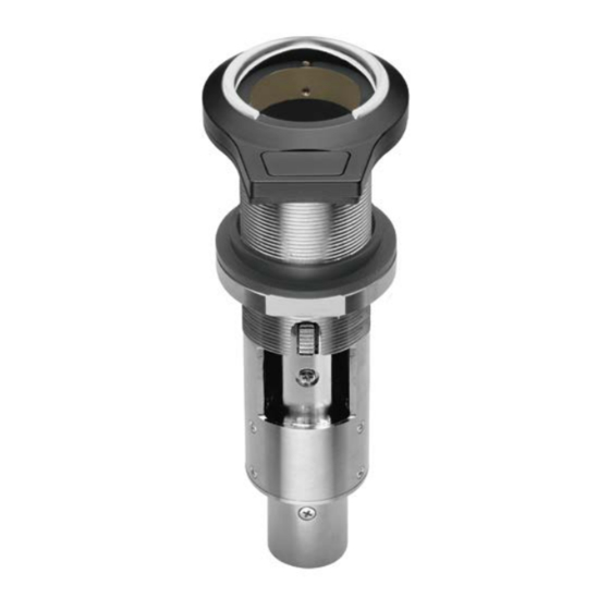
■ Description
The AT8657/LED-S flush-mount microphone socket features a capacitive-type touch-
sensitive switch, Red/Green LED indicator ring, switch logic output for controlling
remote devices and a lock tab to hold microphone in place. The socket is equipped with
a three-pin XLRF-type in, and a five-pin XLRM-type output connector.
The AT8657/LED-S requires 24-48V DC phantom power for operation. The electronics in
the socket take up to 30 seconds to stabilize after power is applied; during this start-up
period, some sonic disturbances may be heard upon switching if the system is "live."
The touch-sensitive switch can be used to trigger an external device.
The lock tab, located in the socket case, automatically engages when microphone is
inserted, securely holding it in place until tab is manually released by user.
The output of the socket is a 5-pin XLRM-type connector.
Isolators are included with the unit for mechanical isolation from the mounting surface.
A retaining ring is also included for use with gooseneck microphones. The socket is
enclosed in a heavy-duty die-cast case. The low-profile housing has a low-reflectance
black finish.
■ Connection procedure
Connect the output terminals of AT8657/LED-S to a device that hava a
microphone input (balanced input) compatible with a phantom power supply,
a switch logic control output and a LED logic input . The input / output connectors are
XLRM-type with polarity as shown in the figure below.
Output terminals
PIN1
PIN5
(ground)
(LED Input)
1
5
3
4
2
PIN2
PIN4
(Audio +)
(Switch Logic)
PIN3 (Audio -)
AT8657/LED-S requires 24-48 V
DC phantom power.
Flush-mount Microphone Socket with LED Ring and Touch Switch AT8657/LED-S
Microphone input terminals
PIN2 (hot)
PIN1 (ground)
PIN3
(cold)
■ Specifications
Output impedance
Switch logic
I/O voltage
LED input
Maximum input voltage
Phantom power requirements
Switch
Weight
Dimensions
Intput connector
Output connector
Accessories furnished
■ Installation and Operation
The AT8657/LED-S requires 24-48V DC phantom power for operation.
Output is low impedance (Lo-Z) balanced. The signal appears across Pins 2 and 3; Pin
1 is ground (shield). Output phase is "Pin 2 hot" - positive acoustic pressure produces
positive voltage at Pin 2. Switch logic output appears between pins 1 and 4. LED logic
input appears between pins 1 and 5.
The microphone socket should be installed on a flat, unobstructed mounting surface.
The AT8657/LED-S should be mounted to a tabletop using the included isolators in
order to dampen surface vibration. To mount the socket with the isolators, a 35 mm
hole is recommended. Place the isolators on either side of the hole to achieve
mechanical isolation from the mounting surface.
The AT8657/LED-S's capacitive-type touch-sensitive switch allows the user to trigger
a function on an external device: Switch logic output is High (+5V DC) when pressed.
Low (0V DC) when not pressed.
The LED indicator ring lights red when logic high (+5V DC) and green when logic low
(0V DC).
■Dimensions
55
10.4
4.1
19.0
Audio-Technica Corporation
2-46-1 Nishi-naruse, Machida, Tokyo 194-8666, Japan
©2017 Audio-Technica Corporation
Global Support Contact: www.at-globalsupport.com
360 Ohms
High (+5V DC) when pressed;
Low (0V DC) when not pressed
-0.5V to 5.5V
Red when high (+5V DC), Green when low (0V DC),
-0.5V to 5.5V
24-48V DC, 4 mA typical
Touch-sensitive control : momentary
165 g
130.6 mm long, 55.0 mm maximum width
3-pin XLRF-type
5-pin XLRM-type
One pair isolators, one set metal retainer ring
(Unit: mm)
Mounting
30.0
20-JAN-2021
Form No.ATGC-L0392-21
Surface
Isolator
(upper)
33.5
Surface
Isolator
(lower)
Nut
Release
Tab
Advertisement

Related Manuals for Audio Technica AT8657/LED-S


Summary of Contents for Audio Technica AT8657/LED-S
- Page 1 The microphone socket should be installed on a flat, unobstructed mounting surface. ■ Features The AT8657/LED-S should be mounted to a tabletop using the included isolators in order to dampen surface vibration. To mount the socket with the isolators, a 35 mm hole is recommended.
- Page 2 165 克 外形尺寸 长 130.6 mm, 最大宽度 55.0 mm 输入端子 3 针卡农母头 输出端子 5 针卡农公头 标准配置 1对防震绝缘胶;1套金属固定环 ■ 安装与操作 AT8657/LED-S 内置的控制电路,需使用直流 24V 至 48V 幻象供电工作。 低阻抗的平衡音频输出,音频信号以卡农公头的2号及3号针脚输出,1号针脚则为 地线(屏蔽)连接。输出相位将以正相位电平设于2号针脚上。开关按钮的逻辑输出 感谢您购买本产品。在使用产品之前,请全文浏览本用户手册以确保您将正确地使用 连接于1号与4号针脚中,LED 输入控制则应用于1号与5号针脚中。 本产品。请妥善保存本手册,以供将来参考。 话筒插座应安装在一个平直及无阻碍物的平面上。 ■ 产品特点 AT8657/LED-S 插座应使用附属的防震胶安装于桌面上,以隔离桌面上震动。在与 防震胶一起安装时,需要开出直径 35mm 的圆孔,而防震胶需要前后两端同时安 • 嵌入式安装的话筒插座,适用于 AT846C / AT846O 或任何使用3针卡农公头输出...