Advertisement
Quick Links
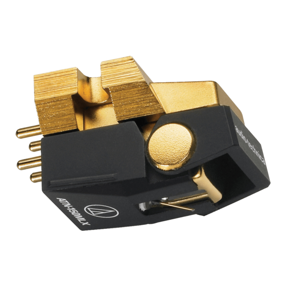
AT150MLX
Vector-Aligned
Stereo Phono Cartridge
Wide Range Vector-Aligned Vibration
System and Improved Paratoroidal Signal Generating
System featuring PCOCC Wire
Vector-Aligned stereo phono cartridges feature an original design
patented by Audio-Technica around the world. The key to this
mechanism is the two magnetic generators arranged in the shape of a
"V". These two magnets are positioned precisely to match the positions
of the left and right channels in the stereo record groove. Major benefits
of the Vector-Aligned cartridge include outstanding channel separation,
very low distortion and superb tracking performance. Incorporating the
same essential merits as other Vector-Aligned models, the AT150MLX
features three additional technological advances:
Boron Cantilever. Its tiny, gold-plated boron cantilever provides an
extremely rigid yet lightweight platform to which the stylus is mounted.
Interestingly, the gold plating acts to damp what little resonance the
boron may produce.
MicroLine
™
Stylus. The stylus used is of the latest and most
advanced design: the MicroLine™ stylus (Figure 1). More closely
resembling the cutter stylus than any previous design, this shape
produces better high frequency response with less wear or distortion
than with earlier configurations.
PCOCC Wire. A technologically advanced pure copper material is
used in Audio-Technica's exclusive "Paratoroidal Signal Generator"
(Figure 2). Together with the laminated core structure, which minimizes
loss in the high frequency region, this integrated paratoroidal generator
system operates at an efficiency significantly greater than conventional
cartridges. The use of PCOCC wire (Pure Copper by Ohno Continuous
Casting) perfects the performance of the advanced paratoroidal coil
design. A special high-temperature extrusion die produces copper with
virtually no transverse crystal barriers to impede signal transmission or
color sound. Thus, the coils of the AT150MLX transmit distortion-free
sound in which even the most subtle details are reproduced with clarity
and purity.
A mu-metal shielding plate between the left and right channels in the
generator system assure that the high level of channel separation
achieved is preserved at the cartridge output.
To further increase the accuracy of the AT150MLX's moving system,
Audio-Technica engineers have ensured against unwanted parasitic
vibration with an anti-resonance ceramic mounting base.
Mu-Metal Shield
Isolated PCOCC
Paratoroidal Coils
Laminated Coil Core with
Unitized Pole Pieces
Vector-Aligned Dual Magnets
Fig. 2
0.3mm Diameter Gold-plated Boron Cantilever
Nude-Mounted Microline Natural Diamond Stylus
™
Fig. 1
Individual Compliance Adjustment Screw
Radial Damping Ring at Cantilever Fulcrum
As a final attention to detail, even the output terminals are
constructed of PCOCC copper. This meticulous care and attention
given to every minute detail in both the vibration and generator
systems has resulted in a significant improvement in the performance
and sound quality. This superb cartridge offers audiophiles and other
serious listeners added musical enjoyment.
Preliminary Installation
Keep stylus guard down. Remove
the stylus assembly by pulling away
from the cartridge body at a slight
rearward angle (Figure 3). Place the
stylus assembly out of harm's way.
Mount the cartridge body to the
tone arm head shell.* Use the
mounting hardware supplied with the cartridge or with the turntable,
and tighten until just snug. Replace the stylus assembly briefly to check
for mechanical interference with mounting hardware. The stylus
assembly should click into place. Again remove the stylus assembly for
safekeeping.
Electrical Connections
Four terminals at the rear of the cartridge are color-coded to match
standard wiring in stereo tone arms (Figure 4). Connect with slip-on
lugs provided on the head shell wiring. NEVER SOLDER TO
CARTRIDGE TERMINALS! Heat applied to the terminals will damage
the internal cartridge wiring.
For monaural operation, the Left
and Right signal terminals should be
connected to the monaural signal
lead, and the Left and Right ground
terminals should be connected to
the ground lead.
Final Adjustment
It is especially important that the
"overhang" and tone arm height should be exactly correct. The stylus
overhang, or distance from the stylus tip to the center of the turntable,
should be 15mm. You can check for correct overhang with the plastic
gauge to which your cartridge is mounted in the packaging.
Replace the stylus assembly; flip the stylus guard up. You should
be certain that the stylus assembly and cartridge body are exactly
perpendicular to the record surface, and that the cartridge is aligned
with the sides of the tone arm for best performance.
If possible, adjust the arm height so that the top of the cartridge is
parallel to the record surface when the stylus is cued down on the
record.
Connection to System
Run two shielded audio cables from the cartridge/tone arm connec-
tions on the turntable to the magnetic phono inputs on the amplifier or
receiver. Observe Left and Right channel markings.
To assure maximum performance, the lowest possible connecting
cable losses between turntable and amplifier are required. Very short
conventional cables may be used.
A separate ground wire usually comes attached to the turntable of
most electronics.
Distorted or unbalanced sound from the two phono channels often
can be traced to wires interchanged or touching at the cartridge
terminals. A reduction in output or muffled sound may result if the
stylus assembly is not fully seated. Hum from the phonograph input
can usually be traced to a bad audio cable or absence of the separate
ground wire from turntable to amplifier.
*Note: These instructions assume that you will be using this cartridge
in conjunction with a tone arm having a universal head shell. If your
tone arm has a different style head shell, follow the instructions
included with your tone arm.
Cartridge
Stylus Assembly
Stylus
Guard
Fig. 3
Left Output (White)
Right Output
(Red)
Right Ground
Left Ground
(Green)
(Blue/Black)
Fig. 4
Advertisement

Related Manuals for Audio Technica AT150MLX


Summary of Contents for Audio Technica AT150MLX
- Page 1 A special high-temperature extrusion die produces copper with virtually no transverse crystal barriers to impede signal transmission or color sound. Thus, the coils of the AT150MLX transmit distortion-free sound in which even the most subtle details are reproduced with clarity and purity.
- Page 2 DIN 45 549/AT6607 test records with bands of carefully calibrated recorded amplitude (one micron equals 0.0001 cm). Program IeveIs of typical commercial recordings are on the order of 60-70 microns. †† 20˚ is lEC/DIN Standard. One Year Limited Warranty AT150MLX 10-30,000 0.75 - 1.75 30/20 †† 23˚...