Advertisement
Quick Links
English
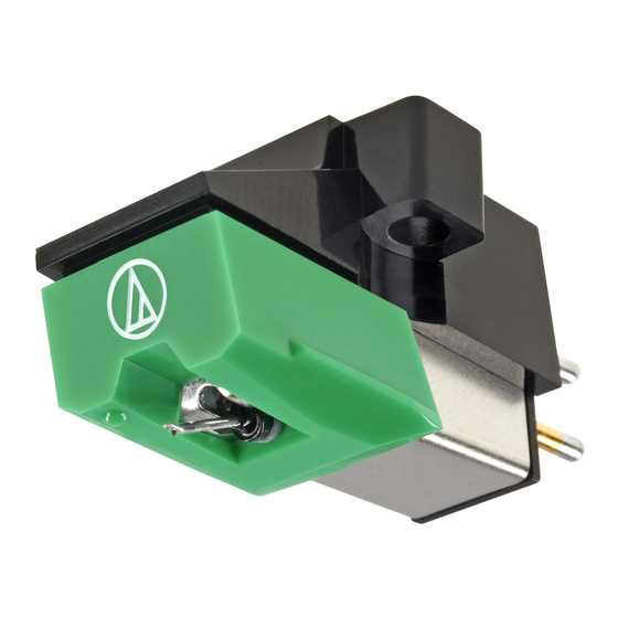
AT95E
Thank you for purchasing this Audio-Technica product. Before using the
product, read through this user manual to ensure that you will use the
product correctly. Please keep this manual for future reference.
User Manual
■ Safety precautions
Dual Moving Magnet Stereo Cartridge
• Keep the plastic bag provided with the product out of the
Cellule stéréo à double aimant mobile
reach of small children and away from open flames to avoid
Dual Moving Magnet Stereo Tonabnehmersystem
accidents or fire.
• Keep the product out of the reach of small children to avoid
Fonorivelatore a Magnete Mobile Stereo
accidents or malfunction.
Cápsula estéreo de imán móvil
• Do not put the product in a location where it is exposed to
direct sunlight, near heating devices, or in places with high
Cápsula Tipo "Moving Magnet" Dual Estéreo
temperatures, high humidity, or high concentrations of dust
Головка звукоснимателя стереофоническая
to avoid malfunction.
с двойным подвижным магнитом
• Do not touch the product's cantilever, stylus tip, and magnets
듀얼 VM 스테레오 카트리지
to avoid malfunction.
• Do not attempt to disassemble or modify the product to avoid
双动磁式立体声唱头
malfunction.
雙動磁 VM 型立體聲唱頭
• Do not subject the product to strong impact to avoid
malfunction.
■ Name of each part
Become familiar with each part before using the product.
1
Protector
2
Cartridge body
3
Output terminals
A
4
Stylus (Replacement stylus)
Rear
5
Cantilever
6
6
Stylus tip
5
4
7
Magnets
7
■ How to use
Remove the (replacement) stylus before mounting the product.
1. Mount the product onto the headshell or headshell-
1
integrated tonearm.
2. Connect the lead tips, noting output polarity.
· Connect headshell lead tips to the product output terminals
2
(as shown in the figure).
3
· Never apply heat (from solder, etc.) to the output terminals.
3. Determine the correct position for installing the product
B
(adjust overhang).
· Adjust overhang following the instructions in the tonearm's,
turntable's, or headshell's user manual.
a
If you are unsure, align the stylus tip to the cartridge
-)
originally attached to the tonearm (as shown in the figure).
Green (
right channel /
Stylus
4. Adjust tracking force.
(Replacement stylus)
Blue ( left channel / -)
· Confirm the tracking force for the product in "Specifications. "
5. Adjust arm height.
White ( left channel / +)
· Adjust the height so that the bottom surface of the headshell
and the record surface are parallel, as seen from the side. An
Screw
Red ( right channel / +)
improper arm height may cause the body of the product to
make contact with the record and could impair audio quality
or damage the record.
6. Connect directly to the PHONO (MM) terminal of the
preamplifier/amplifier.
· If your preamplifier/amplifier does not have a PHONO
Lead tip
terminal, use a phono equalizer (sold separately).
■ Care
b
Cartridge that came
· Use a brush to remove dirt and dust from the stylus tip.
with the turntable
AT95E
· Always move the brush in the direction in which the record
rotates.
· A stylus cleaner (sold separately) is recommended to remove
stubborn dirt.
■ Replacing the stylus
1. Remove the replacement stylus by pulling in the direction
of the arrow without touching the cantilever, stylus tip,
and magnets.
2. Install a new replacement stylus onto the cartridge body.
b
Make this distance as exact as
· Lifetime of the replacement stylus is approx. 300 hours.
possible.
■ Specifications
Type: VM
Frequency response: 20 to 20,000 Hz
C
Output voltage: 3.5 mV (1 kHz, 5 cm/sec.)
Channel separation: 20 dB (1 kHz)
Output balance: 2.0 dB (1 kHz)
Tracking force: 1.5 to 2.5 g (2.0 g standard)
Coil impedance: 2.8 k ohms (1 kHz)
DC resistance: 410 ohms
Recommended load impedance: 47 k ohms
Recommended load capacitance: 100 to 200 pF
Coil inductance: 400 mH (1 kHz)
Static compliance: 20 × 10
Dynamic compliance: 6.5 × 10
Stylus: Elliptical bonded
Stylus curvature radius: 0.3 × 0.7 mil
D
Cantilever: Aluminum pipe
a
Vertical tracking angle: 20°
b
Dimensions: 17 .2 mm (0.68") × 17 .0 mm (0.67") × 30.5 mm (1.20")
(H × W × D)
Weight: 5.7 g (0.20 oz)
Replacement stylus (sold separately): ATN95E
Accessories: Cartridge installation slotted screws 11.0 mm (0.43") × 2 and
8.0 mm (0.31") × 2, Washer × 2, Round nut × 2
Pull.
For product improvement, the product is subject to modification without notice.
Position rear tab.
AT95E_UM_V1_10L_170629.indd 1
Français
Nous vous remercions d'avoir fait l'acquisition de ce produit
Audio-Technica. Avant de l'utiliser, lisez entièrement ce manuel de
l'utilisateur afin de vous assurer que vous utiliserez correctement le
produit. Veuillez conserver ce manuel pour référence future.
■ Précautions de sécurité
• Gardez le sac plastique fourni avec le produit hors de portée
des jeunes enfants et éloigné de flammes afin d'éviter tout
accident ou incendie.
• Gardez le produit hors de portée des jeunes enfants afin
d'éviter tout accident ou dysfonctionnement.
• Ne placez pas le produit dans un endroit où il est exposé aux
rayons directs du soleil, à proximité d'appareils de chauffage,
ou dans des lieux où règnent des températures élevées, une
humidité élevée ou des poussières à forte concentration pour
éviter tout dysfonctionnement.
• Ne touchez pas le cantilever, la pointe de lecture et les
aimants du produit pour éviter tout dysfonctionnement.
• Ne tentez pas de démonter ou d'apporter des modifications
au produit afin d'éviter tout dysfonctionnement.
• Ne soumettez pas le produit à de forts impacts afin d'éviter
tout dysfonctionnement.
A
■ Nom de chaque élément
Familiarisez-vous avec chaque élément avant d'utiliser le produit.
1
Protection
2
Corps de la cellule
3
Bornes de sortie
4
Pointe de lecture (pointe de lecture de remplacement)
5
Cantilever
6
Pointe de lecture
7
Aimants
B
■ Procédure d'utilisation
Retirez la pointe de lecture (de remplacement) avant de procéder
a
à l'installation du produit.
1. Installez le produit sur le porte-cellule ou le bras de lecture
a
intégré au porte-cellule.
a
2. Raccordez les extrémités de fils en notant la polarité de sortie.
· Raccordez les extrémités de fils du porte-cellule aux bornes de
sortie du produit comme indiqué sur l'illustration.
· Ne chauffez jamais (à partir d'une soudure, etc.) les bornes de
b
sortie.
3. Déterminez la position correcte pour l'installation du
produit (réglage de l'avant de la cellule).
· Réglage de l'avant de la cellule en suivant les instructions du
manuel de l'utilisateur du bras de lecture, de la platine ou du
porte-cellule.
En cas de doute, alignez la pointe de lecture à la cellule fixée
initialement au bras de lecture (comme indiqué dans la figure).
4. Réglez la force d'appui.
· Vérifiez la force d'appui du produit en vous référant aux
« Caractéristiques techniques ».
5. Réglez la hauteur du bras.
· Réglez la hauteur de sorte que la surface de fond du porte-cellule
et la surface du disque soient parallèles, comme vu de profil. Une
hauteur du bras incorrecte peut entraîner un contact du corps du
produit avec le disque et peut altérer la qualité audio ou
endommager le disque.
6. Connectez directement à la borne PHONO (MM) du
C
pré-amplificateur/amplificateur.
· Si votre pré-amplificateur/amplificateur n'est pas équipé d'une
borne PHONO, utilisez un égaliseur phono (vendu séparément).
■ Entretien
· Utilisez une brosse adaptée pour enlever les impuretés et la
poussière autour de la pointe de lecture.
D
· Déplacez toujours la brosse dans le sens de rotation de
l'enregistrement.
· Une solution nettoyante pour pointe de lecture (vendue
séparément) est recommandé pour enlever les impuretés
a
persistantes.
■ Remplacement de la pointe de lecture
1. Retirez la pointe de lecture de remplacement en tirant
dans le sens de la flèche sans toucher le cantilever, la
pointe de lecture et les aimants.
2. Installez une nouvelle pointe de lecture de remplacement
sur le corps de la cellule.
b
· La durée de vie de la pointe de lecture de remplacement est
d'environ 300 heures.
■ Caractéristiques techniques
Type : Double Aimant Mobile en V
Réponse en fréquence : 20 Hz à 20 000 Hz
Tension de sortie : 3,5 mV (1 kHz, 5 cm/s.)
Séparation entre les canaux : 20 dB (1 kHz)
-6
cm/dyne
Équilibre des canaux : 2,0 dB (1 kHz)
cm/dyne (100 Hz)
Force d'appui : 1,5 à 2,5 g (2,0 g en standard)
-6
Impédance de la bobine : 2,8 k ohms (1 kHz)
Résistance CC : 410 ohms
Impédance de charge recommandée : 47 k ohms
Capacité de charge recommandée : 100 à 200 pF
Inductance de la bobine : 400 mH (1 kHz)
Compliance statique : 20 × 10
-6
cm/dyne
Compliance dynamique : 6,5 × 10
-6
cm/dyne (100 Hz)
Pointe de lecture : collée, elliptique
Rayon de courbure de la pointe : 0,3 × 0,7 mil
Cantilever : tube en aluminium
Angle de lecture vertical : 20°
Dimensions : 17 ,2 mm × 17 ,0 mm × 30,5 mm (H × L × P)
Poids : 5,7 g
Pointe de lecture de remplacement (vendue séparément) : ATN95E
Accessoires : vis à tête fendue de fixation de la cellule 11 mm × 2 et 8 mm × 2,
rondelle × 2, écrou rond × 2
À des fins d'amélioration, le produit peut être modifié sans préavis.
Deutsch
Vielen Dank für den Kauf dieses Audio-Technica-Produktes. Lesen Sie
vor dem Gebrauch dieses Produktes die Bedienungsanleitung für eine
ordnungsgemäße Nutzung. Bitte bewahren Sie diese Anleitung zum
späteren Nachschlagen auf.
■ Sicherheitshinweise
• Bewahren Sie den Plastikbeutel, der dem Produkt beiliegt,
außerhalb der Reichweite von kleinen Kindern auf und fern
von offenen Feuern, um Unfälle oder Brände zu verhindern.
• Bewahren Sie das Produkt außerhalb der Reichweite von kleinen
Kindern auf, um Unfälle oder Fehlfunktionen zu vermeiden.
• Platzieren Sie das Produkt zur Vermeidung einer Fehlfunktion
nicht an einem Ort, an dem es direktem Sonnenlicht
ausgesetzt ist, in der Nähe von Heizgeräten oder an Orten, an
denen eine hohe Temperatur oder hohe Luftfeuchtigkeit
herrscht oder viel Staub vorhanden ist.
• Berühren Sie zur Vermeidung einer Fehlfunktion nicht den
Nadelträger, die Spitze der Abtastnadel und die Magneten des
Produkts.
• Versuchen Sie zur Vermeidung einer Fehlfunktion nicht das
Produkt auseinanderzubauen oder zu modifizieren.
• Setzen Sie das Produkt zur Vermeidung einer Fehlfunktion
keinen starken Stößen aus.
A
■ Bezeichnung der Teile
Machen Sie sich vor der Verwendung des Produktes mit der
Bezeichnung der Teile vertraut.
1
Schutzkappe
2
Tonabnehmergehäuse
3
Ausgangsklemmen
4
Abtastnadel (Austauschnadel)
5
Nadelträger
6
Spitze der Abtastnadel
7
Magneten
B
■ Verwendung
Entfernen Sie die Abtastnadel (Austauschnadel), bevor Sie das
Produkt befestigen.
1. Befestigen Sie das Produkt am Tonabnehmerkopf oder am
a
integrierten Tonarm.
a
2. Verbinden Sie die Drahtenden unter Beachtung der
Ausgangspolarität.
a
· Verbinden Sie die Drahtenden des Tonabnehmerkopfs mit den
Ausgangsklemmen (wie in der Abbildung gezeigt).
· Setzen Sie die Ausgangsklemmen keiner Wärme aus (von
Lötarbeiten usw.).
b
3. Bestimmen Sie die richtige Position für die Installation des
Produktes (Überhang justieren).
b
· Justieren Sie den Überhang gemäß den Anweisungen in der
Bedienungsanleitung des Tonarms, Plattenspielers oder
Tonabnehmerkopfes.
Wenn Sie unsicher sein sollten, richten Sie die Spitze der
Abtastnadel an dem ursprünglich am Tonarm befestigten
Tonabnehmer aus (wie in der Abbildung dargestellt).
4. Justieren Sie die Auflagekraft.
· Prüfen Sie die Auflagekraft des Produkts unter „Technische Daten" .
5. Justieren Sie die Tonarmhöhe.
· Justieren Sie die Höhe so, dass die Unterseite des
Tonabnehmerkopfs und die Schallplattenoberfläche parallel sind,
wie von der Seite aus betrachtet. Eine falsche Tonarmhöhe kann
eventuell dazu führen, dass das Produktgehäuse die Schallplatte
berührt, wodurch die Audioqualität beeinträchtigt oder die
Schallplatte beschädigt wird.
6. Schließen Sie den Plattenspieler direkt am Phono-Eingang
(MM) des Vorverstärkers/Vollverstärkers an.
· Wenn Ihr Vorverstärker/Vollverstärker keinen PHONO-Anschluss
besitzt, verwenden Sie einen Phono-Equalizer (gesondert erhältlich).
C
■ Pflege
· Verwenden Sie einen Pinsel, um Schmutz und Staub von der
Spitze der Abtastnadel zu entfernen.
· Bewegen Sie den Pinsel immer in Drehrichtung der Schallplatte.
· Ein Abtastnadelreiniger (separat erhältlich) wird für die
Entfernung von hartnäckigem Schmutz empfohlen.
■ Austauschen der Nadel
D
1. Nehmen Sie die Austauschnadel ab, indem Sie sie in
Pfeilrichtung abziehen, ohne den Nadelträger, die Spitze
der Abtastnadel und die Magneten zu berühren.
a
2. Setzen Sie eine neue Austauschnadel in den Tonabnehmer
ein.
b
· Die Lebensdauer einer Austauschnadel beträgt etwa 300 Stunden.
■ Technische Daten
Typ: VM
Frequenzgang: 20 bis 20.000 Hz
Ausgangsspannung: 3,5 mV (1 kHz, 5 cm/Sek.)
Kanaltrennung: 20 dB (1 kHz)
Ausgangsbalance: 2,0 dB (1 kHz)
Auflagekraft: 1,5 bis 2,5 g (2,0 g Standard)
Spulenimpedanz: 2,8 kOhm (1 kHz)
DC-Widerstand: 410 Ohm
Empfohlene Lastimpedanz: 47 kOhm
Empfohlene Lastkapazität: 100 bis 200 pF
Spuleninduktivität: 400 mH (1 kHz)
Statische Compliance: 20 × 10
cm/dyne
-6
Dynamische Compliance: 6,5 × 10
-6
cm/dyne (100 Hz)
Abtastnadel: Elliptisch, verklebt
Rundungsradius der Nadel: 0,3 × 0,7 mil
Nadelträger: Aluminiumrohr
Vertikaler Abtastwinkel: 20°
Abmessungen: 17 ,2 mm × 17 ,0 mm × 30,5 mm (H × B × T)
Gewicht: 5,7 g
Austauschnadel (gesondert erhältlich): ATN95E
Zubehör: Tonabnehmer-Befestigungsschrauben (Schlitzschrauben) 11,0 mm × 2
und 8,0 mm × 2, Abstandshalter × 2, Rundmutter × 2
Produktänderungen zu Zwecken der Produktverbesserung ohne Ankündigung
vorbehalten.
Italiano
Grazie per aver acquistato questo prodotto Audio-Technica. Prima di
utilizzare il prodotto, leggere con cura questo manuale dell'utente per
essere certi di utilizzare correttamente il prodotto. Si prega di
conservare il presente manuale in modo da poterlo consultare in futuro.
■ Precauzioni di sicurezza
• Conservare la busta di plastica fornita col prodotto lontano
dai bambini e da fiamme vive per evitare incidenti o incendi.
• Conservare la busta di plastica lontano dai bambini per
evitare incidenti o problemi di funzionamento.
• Non posizionare il prodotto in luoghi in cui è esposto alla luce
diretta del sole, vicino a dispositivi di riscaldamento o in
luoghi con temperature elevate, umidità, o alte concentrazioni
di polvere per evitare problemi di funzionamento.
• Non toccare l'elemento a sbalzo, la puntina o i magneti per
evitare problemi di funzionamento.
• Non smontare o modificare il prodotto per evitare problemi di
funzionamento.
• Evitare di sbattere il prodotto per evitare problemi di
funzionamento.
■ Nome di ciascun componente
A
Familiarizzare con ciascun componente prima di utilizzare il
A
prodotto.
1
Protezione
2
Corpo della capsula
3
Terminali di uscita
4
Puntina (puntina sostitutiva)
5
Elemento a sbalzo
6
Puntina
7
Magneti
■ Modalità d'uso
B
Prima di montare il prodotto, rimuovere la puntina (sostitutiva).
B
1. Montare il prodotto sulla testina sagomata o sul braccio
porta-testina.
a
2. Collegare le punte dei cavi, rispettando la polarità indicata
di uscita.
a
· Collegare le punte dei cavi della testina sagomata ai terminali di
uscita del prodotto (come mostrato in figura).
· Non usare calore (da saldatura, ecc.) sui terminali di uscita.
3. Stabilire la posizione corretta per installare il prodotto
(regolare la sporgenza).
b
· Regolare la sporgenza seguendo le istruzioni nel manuale
dell'utente del braccio, del giradischi o della testina sagomata.
Se non si è sicuri allineare la puntina con la capsula attaccata
originariamente al braccio con la puntina (come illustrato nella
figura).
4. Regolare la forza di tracciamento.
· Confermare la forza di tracciamento per il prodotto come descritto
in "Specifiche tecniche" .
5. Regolare l'altezza del braccio.
· Regolare l'altezza in modo che la superficie inferiore della testina
sagomata e la superficie del disco si trovino in parallelo, come si
vede lateralmente. Un'altezza del braccio inappropriata può
provocare il contatto della struttura del prodotto con il disco
rovinando la qualità audio o danneggiare il disco.
6. Collegare direttamente il terminale PHONO (MM) al
preamplificatore/amplificatore.
· Se il preamplificatore/amplificatore non dispone di un terminale
PHONO, utilizzare un equalizzatore phono (in vendita
separatamente).
■ Manutenzione
C
· Utilizzare la spazzola per togliere sporco e polvere dalla puntina.
C
· Spostare sempre la spazzola nella direzione in cui ruota il disco.
· Un detergente per puntine (in vendita separatamente) è
consigliato per togliere lo sporco ostinato.
■ Sostituzione della puntina
D
1. Rimuovere la puntina sostitutiva tirando nella direzione
della freccia senza toccare l'elemento a sbalzo, la puntina
D
e i magneti.
a
2. Installare la puntina sostitutiva sul corpo della capsula.
b
· La durata della cartuccia sostitutiva è di circa 300 ore di utilizzo.
a
■ Specifiche tecniche
Tipo: VM
Risposta in frequenza: da 20 a 20.000 Hz
Tensione in uscita: 3,5 mV (1 kHz, 5 cm/sec.)
Separazione dei canali: 20 dB (1 kHz)
Bilanciamento di uscita: 2,0 dB (1 kHz)
Forza di tracciamento: da 1,5 a 2,5 g (2,0 g standard)
Impedenza bobina: 2,8 k Ohm (1 kHz)
Resistenza CC: 410 Ohm
Carico di impedenza consigliato: 47 k Ohm
Carico di capacitanza consigliato: da 100 a 200 pF
Induttanza della bobina: 400 mH (1 kHz)
Conformità statica: 20 × 10
-6
cm/dyne
Conformità dinamica: 6,5 × 10
-6
cm/dyne (100 Hz)
Puntina: ellittica incollata
Raggio di Curvatura della puntina: 0,3 × 0,7 mil
Cantilever: tubo in alluminio
Angolo di tracciatura verticale: 20°
Dimensioni: 17 ,2 mm × 17 ,0 mm × 30,5 mm (A × L × P)
Peso: 5,7 g
Puntina sostitutiva (in vendita separatamente): ATN95E
Accessori: Viti a taglio per installazione della capsula 11,0 mm × 2 e 8,0 mm × 2,
rondella × 2, dado rotondo × 2
Per garantire un continuo miglioramento, il prodotto è soggetto a modifiche
senza preavviso.
Español
Gracias por adquirir este producto de Audio-Technica. Antes de utilizar
el producto, lea detenidamente este manual del usuario para
asegurarse de que usa el producto correctamente. Guarde este
manual para poder consultarlo en el futuro.
■ Precauciones de seguridad
• Mantenga la bolsa de plástico en la que se suministra el
producto fuera del alcance de los niños y lejos de fuegos,
para evitar accidentes o un incendio.
• Mantenga el producto fuera del alcance de los niños, para
evitar accidentes o un fallo de funcionamiento.
• No coloque el producto en una ubicación donde esté
expuesto a la luz solar directa, cerca de dispositivos de
calefacción, o en lugares con alta temperatura, humedad
elevada o alta concentración de polvo, para evitar fallos de
funcionamiento.
• No toque el cantilever, la punta de la aguja ni los imanes para
evitar fallos de funcionamiento.
• No intente desmontar ni modificar el producto para evitar
fallos de funcionamiento.
• No someta el producto a impactos fuertes, para evitar fallos
de funcionamiento.
■ Identificación de la piezas
A
Familiarícese con cada pieza antes de utilizar el producto.
1
Protector
2
Cuerpo de la cápsula
3
Terminales de salida
4
Aguja (aguja de repuesto)
5
Cantilever
6
Punta de la aguja
7
Imanes
■ Cómo utilizarlo
B
Extraiga la aguja (de repuesto) antes de montar el producto.
1. Monte el producto en el portacápsulas o en el brazo
fonocaptor integrado en el portacápsulas.
a
2. Conecte las puntas del conductor, comprobando la polaridad
de salida.
a
· Conecte las puntas del conductor del portacápsulas a los
terminales de salida del producto (como se muestra en la figura).
· No aplique nunca calor (de soldadura, etc.) a los terminales de
salida.
3. Determine la posición correcta para instalar el producto
(ajuste la proyección).
b
· Ajuste la proyección siguiendo las instrucciones del manual del
usuario del brazo fonocaptor, del giradiscos o del portacápsulas.
Si no está seguro, alinee la punta de la aguja con la cápsula
originalmente unida al brazo fonocaptor (como se muestra en la
figura).
4. Ajuste la fuerza de seguimiento.
· Verifique la fuerza de seguimiento del producto en el apartado
"Especificaciones" .
5. Ajuste la altura del brazo.
· Ajuste la altura de forma que la superficie inferior del
portacápsulas y la superficie del disco estén paralelas, según se ve
desde el lateral. Una altura del brazo incorrecta puede hacer que el
cuerpo del producto esté en contacto con el disco y eso podría
afectar a la calidad de audio o dañar el disco.
6. Conecte el producto directamente al terminal PHONO
(MM) del preamplificador/amplificador.
· Si su preamplificador/amplificador no cuenta con un terminal
PHONO, utilice un ecualizador phono (se vende por separado).
■ Cuidados
C
· Utilice un cepillo para eliminar el polvo y la suciedad de la punta
de la aguja.
· Siempre mueva el cepillo en la dirección en que gira el disco.
· Se recomienda un limpiador de agujas (se vende por separado)
para eliminar la suciedad más incrustada.
■ Sustitución de la aguja
D
1. Extraiga la aguja de repuesto tirando en dirección de la
flecha sin tocar el cantilever, la punta de la aguja ni los
imanes.
a
2. Instale una nueva aguja de repuesto en el cuerpo de la
cápsula.
b
· La aguja de repuesto tiene una vida útil de unas 300 horas.
■ Especificaciones
Tipo: VM
Respuesta en frecuencia: 20 a 20.000 Hz
Voltaje de salida: 3,5 mV (1 kHz, 5 cm/s)
Separación entre canales: 20 dB (1 kHz)
Balance de salida: 2,0 dB (1 kHz)
Fuerza de seguimiento: 1,5 a 2,5 g (2,0 g estándar)
Impedancia de la bobina: 2,8 kohmios (1 kHz)
Resistencia de CC: 410 ohmios
Impedancia de entrada recomendada: 47 kohmios
Capacitancia de entrada recomendada : 100 a 200 pF
Inductancia de la bobina: 400 mH (1 kHz)
Compensación estática: 20 × 10
-6
cm/dinas
Compensación dinámica: 6,5 × 10
-6
cm/dinas (100 Hz)
Aguja: elíptica pegada
Radio de curvatura de la aguja: 0,3 × 0,7 mil
Cantilever: tubo de aluminio
Ángulo de seguimiento vertical: 20°
Dimensiones: 17 ,2 mm × 17 ,0 mm × 30,5 mm (Al × An× F)
Peso: 5,7 g
Aguja de repuesto (se vende por separado): ATN95E
Accesorios: tornillos ranurados de instalación de la cápsula 11,0 mm × 2 y
8,0 mm × 2, arandela × 2, tuerca redonda × 2
Con el fin de mejorar el producto, este está sujeto a modificaciones sin previo
aviso.
2017/07/20 9:41
Advertisement

Related Manuals for Audio Technica AT95E


Summary of Contents for Audio Technica AT95E
- Page 1 Italiano Español AT95E Thank you for purchasing this Audio-Technica product. Before using the Nous vous remercions d’avoir fait l’acquisition de ce produit Vielen Dank für den Kauf dieses Audio-Technica-Produktes. Lesen Sie Grazie per aver acquistato questo prodotto Audio-Technica. Prima di Gracias por adquirir este producto de Audio-Technica.
- Page 2 Audio-Technica 제품을 구입해 주셔서 감사합니다. 제품을 올바르게 사용할 感谢您购买本款Audio-Technica产品。使用本产品之前,请通读本用户 感謝您購買本 Audio-Technica 產品。使用前,請務必詳閱本使用說明 Rear Obrigado por comprar este produto da Audio-Technica. Antes de usar o Благодарим вас за покупку этого изделия компании Audio-Technica. 수 있도록 제품 사용 전에 본 사용설명서 자세히 읽어 주십시오. 본 설명서를 手册以确保正确使用本产品。请妥善保存本手册,以便日后查阅。...