Table of Contents
Advertisement
Quick Links
Operator's Manual
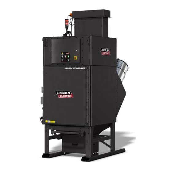
PRISM COMPACT
Register your machine:
www.lincolnelectric.com/register
Authorized Service and Distributor Locator:
www.lincolnelectric.com/locator
Save for future reference
Date Purchased
Code: (ex: 10859)
Serial: (ex: U1060512345)
IM10556-A
|
Issue D ate Jul - 21
© Lincoln Global, Inc. All Rights Reserved.
®
For use with machines having Code Numbers:
13022, 13023, 13024, 13025,
13026, 13027, 13028, 13029,
13061, 13130, 13131, 13132,
13133, 13134, 13135, 13136,
13137, 13138
Need Help? Call 1.888.935.3877
to talk to a Service Representative
Hours of Operation:
8:00 AM to 6:00 PM (ET) Mon. thru Fri.
After hours?
Use "Ask the Experts" at lincolnelectric.com
A Lincoln Service Representative will contact you
no later than the following business day.
For Service outside the USA:
Email: globalservice@lincolnelectric.com
Advertisement
Table of Contents
Troubleshooting

Related Manuals for Lincoln Electric PRISM COMPACT


Summary of Contents for Lincoln Electric PRISM COMPACT
- Page 1 Operator’s Manual PRISM COMPACT ® For use with machines having Code Numbers: 13022, 13023, 13024, 13025, 13026, 13027, 13028, 13029, 13061, 13130, 13131, 13132, 13133, 13134, 13135, 13136, 13137, 13138 Need Help? Call 1.888.935.3877 Register your machine: to talk to a Service Representative www.lincolnelectric.com/register...
- Page 2 THANK YOU FOR SELECTING A QUALITY PRODUCT BY KEEP YOUR HEAD OUT OF THE FUMES. DON’T get too close to the arc. LINCOLN ELEC TRIC. Use corrective lenses if necessary to stay a reasonable distance away from the arc. READ and obey the Safety Data PLEASE EXAMINE CARTON AND EQUIPMENT FOR Sheet (SDS) and the warning label DAMAGE IMMEDIATELY...
- Page 3 W117.2. A Free copy of “Arc Welding Safety” booklet E205 is available from the Lincoln Electric Company, 22801 2.d. All welders should use the following procedures in order to St. Clair Avenue, Cleveland, Ohio 44117-1199.
- Page 4 SAFETY ELECTRIC SHOCK ARC RAYS CAN BURN. CAN KILL. 3.a. The electrode and work (or ground) circuits are 4.a. Use a shield with the proper filter and cover plates to protect your electrically “hot” when the welder is on. Do eyes from sparks and the rays of the arc when welding or not touch these “hot”...
- Page 5 SAFETY WELDING AND CUTTING CYLINDER MAY EXPLODE IF SPARKS CAN CAUSE DAMAGED. FIRE OR EXPLOSION. 7.a. Use only compressed gas cylinders containing the correct shielding gas for the process used 6.a. Remove fire hazards from the welding area. If and properly operating regulators designed for this is not possible, cover them to prevent the welding sparks the gas and pressure used.
- Page 6 ® PRISM COMPACT SAFETY As a rule of thumb, for many mild steel electrode, if the air is (Permissible Exposure Limit), and the recommended guideline, the visibly clear and you are comfortable, then the ventilation is ACGIH TLV (Threshold Limit Value), for many compounds found in generally adequate for your work.
- Page 7 TLV and PEL values are as of October 2013. Always check Safety and 313 of the Emergency Planning and Community Right- Data Sheet (SDS) with product or on the Lincoln Electric website at to-Know Act of 1986 and of 40CFR 370 and 372.
-
Page 8: Table Of Contents
® PRISM COMPACT TABLE OF CONTENTS INSTALLATION .............................SECTION A TECHNICAL SPECIFICATIONS .............................A-1 GENERAL DESCRIPTION.............................A-2 THE INTENDED PURPOSE............................A-2 TRANSPORT AND ERECTION ............................A-2 SELECT SUITABLE LOCATION.............................A-2 ENVIRONMENTAL AREA .............................A-2 INSTALLATION OF PRISM® COMPACT........................A-3 ELECTRICAL CONNECTIONS............................A-6 OPERATION ..............................SECTION B SAFETY PRECAUTIONS...............................B-1 USERS ................................B-1... -
Page 9: Technical Specifications
® TECHNICAL SPECIFICATIONS PRISM COMPACT TECHNICAL SPECIFICATIONS PRISM® COMPACT: AD2455-1, AD2455-3, AD2455-5 AD2455-7 & AD2455-9 GENERAL TYPE OF CLEANING Pulse jet INPUT VOLTAGE 380-480V/3~/50-60Hz DUTY CYCLE 100% NOMINAL +/- 10% COMPRESSED AIR PRESSURE 72 - 87 psi (5 - 6 bar) MAXIMUM CURRENT 7.5 A... -
Page 10: General Description
® INSTALLATION PRISM COMPACT INSTALLATION WARNING Excluded Uses! GENERAL DESCRIPTION • Welding fumes containing oil • Aluminium dust Prism® Compact is a reduced-footprint fan/ ltration unit combination designed with robotic welding and plasma cutting • Burning or incandescent materials system in mind. The 4- lter con gurations can provide extraction •... -
Page 11: Installation Of Prism® Compact
® INSTALLATION PRISM COMPACT FIGURE A.2 INSTALLATION OF PRISM® COMPACT (AD2455-1, AD2455-9 ONLY AD2455-2, AD2455-5, AD2455-6, & AD2455-9 ONLY) TOOLS NEEDED • 5/16" Nutdriver • 9/16" Nutdriver • Ladder/Lift • Drill + 1/4" Drill Bit Step 1 – Remove The 4X4 Wood Frame Remove lag bolts and discard 4X4 wood frame. - Page 12 ® INSTALLATION PRISM COMPACT Step 4 – Install Pitot Tube a. Drill 1/4” hole into the 16” straight duct pipe 40-50” away from the inlet of the unit. b. Insert pitot tube and secure it with 2 sheet metal screws (screws included).
- Page 13 ® INSTALLATION PRISM COMPACT c. Install new lters. FIGURE A.7 Step 5 - Install Filters (See section D for filter 1. Slide lters replacement instructions) into unit as shown, WARNING making sure they are pushed Before opening door, unit must be off and the power...
-
Page 14: Electrical Connections
® INSTALLATION PRISM COMPACT ELECTRICAL CONNECTIONS Make all electrical connections compatible to your local city / state code. WARNING ELECTRIC SHOCK can kill. • Only quali ed personnel should perform this installation. • Turn the input power OFF and unplug the machine from the receptacle before working on this equipment. -
Page 15: Operation
WARNING RESTRICTIONS Only use the product for the welding The Lincoln Electric ”BANK” system may only be used for ltration processes described in the General of fumes and dust generated by some dry processing industries. Description. Avoid using the product for Max 80°C (176°F) gas temperature. -
Page 16: Control
® OPERATION PRISM COMPACT Display System Control Panel CONTROL The Eaton 2DD Smartwire I/O pack produces both an input and an FIGURE B.2 output when connected to a robotic welding cell. When the unit is powered on and operating, the remote output will produce a 24VDC "running"... -
Page 17: Software Description
Online maximum (60Hz) speeds. Consult the tablet operation guide, or cleaning will not stop until the lter pressure falls below contact Lincoln Electric service department for guidance with the Delta P level. adjustment of the fan parameters. -
Page 18: Smartwire Device Learning
Consult Lincoln Electric Field Service to shorten the learning curve. Of vital importance is the initial PID value setting for the air ow. This... -
Page 19: Accessories
® ACCESSORIES PRISM COMPACT ACCESSORIES REPLACEMENT FILTER OPTIONS · KP4519-1 - MERV 11-rated lter cartridge featuring spun bond polyester media construction. · KP4519-2 - MERV 16-rated (high ef ciency) lter cartridge featuring nano bers. · KP4519-3 - MERV 16-rated (high ef ciency) lter cartridge featuring a thermal bonded PTFE membrane. -
Page 20: Prism® Compact Thermal Suppression Overview
® ACCESSORIES PRISM COMPACT PRISM® COMPACT THERMAL SUPPRESSION (AD2455-3, AD2455-4, AD2455-7, AD2455-8 ONLY) OVERVIEW Exhaust/ Warning/ The Prism® Compact indirect low Return Air Diagnostic Light pressure thermal suppression system Damper uses an extinguishing agent commonly known as Novec 1230. It is a colorless... - Page 21 ® ACCESSORIES PRISM COMPACT FIGURE C.2 INSTALLATION OF PRISM® COMPACT WITH THERMAL SUPPRESSION TOOLS NEEDED 5/16” Nut Driver 3/8” Nut Driver 9/16” Nut Driver Ladder/Lift Drill + 1/4” Drill Bit STEP 1 – Remove pallet. Remove lag bolts from unit and fan silencer/damper.
- Page 22 ® ACCESSORIES PRISM COMPACT STEP 6 – Connect the 2m long green cable from the Warning/ Diagnostic Light stack to the connection bulkhead on the back of the clean air box of the machine. STEP 7 - Connect the 2m long green cable from the Warning/ Diagnostic Light stack to the Lincoln Smart Connect Module on the outlet silencer/damper.
-
Page 23: Activation
® ACCESSORIES PRISM COMPACT ACTIVATION OPERATION & DIAGNOSTICS STEP 1 – With the ball valve on the suppressant tank still closed, NORMAL OPERATION DESCRIPTION remove the detection tubing pressure gauge and replace with the A Prism® Compact with thermal suppression has active lling adapter included in the Nitrogen charge kit. -
Page 24: Discharge And Recovery
After the system has been repaired, it must be re-commissioned. watching the LEDs on the module to con rm the input is “seen” This can be done by a Lincoln Electric Field Service Technician. A by it. proper nitrogen charge kit can be used to recharge the detection... - Page 25 3. Press reset on main control panel. The unit is now ready for operation. open. Contact a Lincoln Electric technician for possible temporary resolutions Exhaust Damper Alarm 1. After fan is started, exhaust 1. Repair damper. Possible causes include failed actuator, failed actuator damper located under fan fails switch, obstruction in damper, loose actuator connection to damper.
-
Page 26: Maintenance
(PPE) such as gloves, respirators and instructions, contact your local Lincoln Electric repre- protective clothing to protect against sentative for service options or contact Lincoln Electric overexposure to particulate. It is Customer Service. recommended that a vacuum cleaner or wet methods be used to clean up any loose particulate that is present in ELECTRIC SHOCK can kill. -
Page 27: Periodic Maintenance
PERIODIC MAINTENANCE MAINTENANCE SCHEDULE The product has been designed to function without problems for NOTE: * REQUIRES Lincoln Electric factory authorized service many hours with minimal maintenance. In order to ensure this, technician. some simple, regular maintenance and cleaning activities are AS NEEDED required which are described in this section. -
Page 28: Replacing Filter Cartridges Or Emptying Dustbins
® ® PRISM COMPACT PRISM COMPACT MAINTENANCE • Check fan motor blades for encrusted particles and clean if necessary. • Inspect and clean control panel with a non-aggressive detergent. • Check inlets and outlets for tears or wear. CONTROL PANEL •... -
Page 29: Replacing Filter Cartridges
® PRISM COMPACT MAINTENANCE REPLACING FILTER CARTRIDGES WARNING Before opening door, unit must be off and the power switch on the control panel turned to the off position. Verify power has been switched off at the control panel, then unlock door latches using the supplied hex tool or any standard 5/16"... - Page 30 ® PRISM COMPACT MAINTENANCE REPLACING PRE-FILTERS WARNING Before removing cover plates, unit must be off and the power switch on thecontrol panel turned to the off position. Verify power has been switched off at the control panel, then from either side of the unit, remove 16 - 1/4” bolts with a 5/16”...
- Page 31 ® PRISM COMPACT MAINTENANCE REMOVING AND INSTALLING THE DUST BIN a. Removing the dust bin. FIGURE D.7 1. Lift handle. 2. Rotate left and right latches outward and let handle drop down. 3. Pull dust bin out from under machine.
- Page 32 TROUBLESHOOTING TROUBLESHOOTING GUIDE Service and Repair should only be performed by Lincoln Electric Factory Trained Personnel. Unauthorized repairs performed on this equipment may result in danger to the technician and machine operator and will invalidate your factory warranty. For your safety and to avoid ELECTRICAL SHOCK, please observe all safety notes and precautions detailed throughout this manual.
-
Page 33: Troubleshooting
Cleaning valve fails to open. 1. The pulsation cycle may be faulty. 1. Verify that the pulsation cycle is OK, that it's within the parameters recommended by Lincoln Electric. 2. Possible dirt in the housing of the valve. 2. Clean the housing of the valve. - Page 34 ® PRISM COMPACT TROUBLESHOOTING Observe all Safety Guidelines detailed throughout this manual Observe all Safety Guidelines detailed throughout this manual PROBLEMS POSSIBLE RECOMMENDED (SYMPTOMS) CAUSE COURSE OF ACTION FUNCTION PROBLEMS Filter replacement alarm does 1. Wrong DP reading reported by 1.
- Page 35 ® PRISM COMPACT TROUBLESHOOTING Observe all Safety Guidelines detailed throughout this manual Observe all Safety Guidelines detailed throughout this manual PROBLEMS POSSIBLE RECOMMENDED (SYMPTOMS) CAUSE COURSE OF ACTION FUNCTION PROBLEMS Poor suction. 1. Outlet(s) are blocked. 1. Replace lter if necessary.
- Page 36 PRISM™ COMPACT DIAGRAMS...
- Page 37 PRISM™ COMPACT DIAGRAMS...
- Page 38 PRISM™ COMPACT DIAGRAMS...
- Page 39 PRISM™ COMPACT DIAGRAMS...
- Page 40 PRISM™ COMPACT DIAGRAMS...
- Page 41 PRISM™ COMPACT DIAGRAMS...
- Page 42 PRISM™ COMPACT DIAGRAMS...
- Page 43 PRISM™ COMPACT DIAGRAMS...
- Page 44 PRISM™ COMPACT DIAGRAMS...
- Page 45 PRISM™ COMPACT DIAGRAMS F-10...
- Page 46 PRISM™ COMPACT DIAGRAMS F-11...
- Page 47 ® PRISM COMPACT DIAGRAMS F-12...
- Page 48 ® PRISM COMPACT DIAGRAMS F-13...
- Page 49 ® PRISM COMPACT DIAGRAMS F-14...
- Page 50 ® PRISM COMPACT DIAGRAMS F-15...
- Page 51 ® PRISM COMPACT DIAGRAMS F-16...
- Page 52 ® PRISM COMPACT DIAGRAMS F-17...
- Page 53 ® PRISM COMPACT DIAGRAMS F-18...
- Page 54 PRISM® COMPACT DIAGRAMS F-19...
- Page 55 PRISM® COMPACT DIAGRAMS F-20...
- Page 56 PRISM® COMPACT DIAGRAMS F-21...
- Page 57 PRISM® COMPACT DIAGRAMS F-22...
- Page 58 PRISM® COMPACT DIAGRAMS F-23...
- Page 59 PRISM® COMPACT DIAGRAMS F-24...
- Page 60 PRISM® COMPACT DIAGRAMS AD2455-1 12.8 64.0 69.9 43.0 36.0 62.5 SECTION K-K 44.6 16" INLET 114.0 95.8 60.7 69.1 F-25...
- Page 61 PRISM® COMPACT DIAGRAMS AD2455-2 12.8 64.0 71.8 43.0 36.0 62.5 SECTION K-K 44.6 16" INLET 114.0 95.8 60.78 71.1 F-26...
- Page 62 PRISM® COMPACT DIAGRAMS AD2455-3 12.8 64.0 81.4 43.0 36.0 62.5 44.6 SECTION K-K 52.8 16 IN. INLET 119.8 95.7 72.1 80.6 F-27...
- Page 63 PRISM® COMPACT DIAGRAMS AD2455-4 12.8 62.5 81.4 43.0 36.0 62.5 SECTION K-K 44.6 52.8 16 IN. INLET 119.8 95.8 72.2 80.6 F-28...
- Page 64 PRISM® COMPACT DIAGRAMS AD2455-5 64.0 69.9 43.0 36.0 62.5 SECTION K-K 44.6 114.0 95.8 16" INLET 38.5 69.1 F-29...
- Page 65 PRISM® COMPACT DIAGRAMS AD2455-6 64.0 71.8 43.0 36.0 62.5 SECTION K-K 44.6 114.0 95.8 16" INLET 38.50 71.1 F-30...
- Page 66 PRISM® COMPACT DIAGRAMS AD2455-7 12.8 64.0 81.2 43.0 36.0 62.5 44.6 SECTION K-K 52.8 119.8 95.7 16 IN. INLET 27.3 80.4 F-31...
- Page 67 PRISM® COMPACT DIAGRAMS AD2455-8 12.8 62.5 81.2 43.0 36.0 62.5 SECTION K-K 44.6 52.8 119.8 95.8 16 IN. INLET 27.3 80.4 F-32...
- Page 68 PRISM® COMPACT DIAGRAMS AD2455-9 12.8 64.0 69.9 43.0 36.0 62.5 SECTION K-K 44.6 16" INLET 107.8 95.7 60.7 69.1 F-33...
- Page 69 This page intentionally left blank...
- Page 70 This page intentionally left blank...
- Page 71 WARNING Do not touch electrically live parts or Keep flammable materials away. Wear eye, ear and body protection. electrode with skin or wet clothing. Insulate yourself from work and AVISO DE ground. Spanish PRECAuCION No toque las partes o los electrodos Mantenga el material combustible Protéjase los ojos, los oídos y el bajo carga con la piel o ropa moja-...
- Page 72 WARNING Keep your head out of fumes. Turn power off before servicing. Do not operate with panel open or Use ventilation or exhaust to guards off. remove fumes from breathing zone. AVISO DE Spanish PRECAuCION Los humos fuera de la zona de res- Desconectar el cable de ali- No operar con panel abierto o piración.
- Page 73 TLV limits. Lincoln Electric is not in a position to warrant or guarantee such advice, and assumes no liability, with respect to such information or advice. We expressly disclaim any warranty of any kind, including any warranty of fitness for any customer’s particular...