Riello RLS 70 Installation, Use And Maintenance Instructions
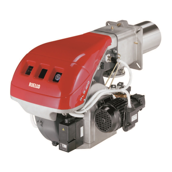
Dual fuel gas-oil/gas burner
Hide thumbs
Also See for RLS 70:
- Manual (64 pages) ,
- Installation, use and maintenance instructions (64 pages) ,
- Installation instruction (44 pages)
Table of Contents
Advertisement
Istruzioni per installazione, uso e manutenzione
Montage und Bedienungs Anleitung
Installation, use and maintenance instructions
Manuel dÕentretien
Bruciatori policombustibile gasolio/gas
I
Mehrstoffbrenner Heizšl/Gas
D
Dual fuel Gas-Oil/Gas burners
GB
Bržleurs mixtes Þoul/gaz
F
Funzionamento bistadio
ZweistuÞger Betrieb
Two-stage operation
Fonctionnement ˆ deux allures
CODICE - CODE
3485000
3485200
3485400
MODELLO - MODELL
MODEL - MODELE
RLS 70
RLS 100
RLS 130
TIPO - TYP
TYPE - TYPE
687 T1
688 T1
689 T1
2915562 2-98
Advertisement
Table of Contents

Related Manuals for Riello RLS 70


Summary of Contents for Riello RLS 70
- Page 1 ZweistuÞger Betrieb Two-stage operation Fonctionnement ˆ deux allures MODELLO - MODELL TIPO - TYP CODICE - CODE MODEL - MODELE TYPE - TYPE 3485000 RLS 70 687 T1 3485200 RLS 100 688 T1 3485400 RLS 130 689 T1 2915562 2-98...
- Page 3 INDICE INHALT GASOLIO / GAS HEIZ…L / GAS Dati tecnici ........pagina 4 Technische Angaben.
-
Page 4: Dati Tecnici
L = testa standard L1 = testa lunga ottenibile con il kit COD. 3010162 L = 250 mm L1 = 385 mm ¥ RLS 70 COD. 3010163 L = 250 mm L1 = 385 mm ¥ RLS 100 COD. 3010164... -
Page 5: Technische Angaben
KIT ZUR VERL€NGERUNG DES FLAMMKOPFES L = StandardlŠnge L1 = Mit Kit erreichbare LŠnge COD. 3010162 L = 250 mm L1 = 385 mm ¥ RLS 70 COD. 3010163 L = 250 mm L1 = 385 mm ¥ RLS 100 COD. 3010164... -
Page 6: Technical Data
KIT FOR LENGTHNING THE COMBUSTION HEAD L = Standard length L1 = Lenght obtainable with the kit COD. 3010162 L = 250 mm L1 = 385 mm ¥ RLS 70 COD. 3010163 L = 250 mm L1 = 385 mm ¥ RLS 100 COD. 3010164... - Page 7 L = longueur standard L1 = longueur pouvant •tre obtenue avec le kit COD. 3010162 L = 250 mm L1 = 385 mm ¥ RLS 70 COD. 3010163 L = 250 mm L1 = 385 mm ¥ RLS 100 COD. 3010164...
-
Page 8: Descrizione Bruciatore
28 Viti per il Þssaggio ventilatore al manicotto 29 Cellula UV 30 Commutatore olio - gas Vi sono due possibilitˆ di blocco del bruciatore: Blocco apparecchiatura: lÕaccensione del pul- RLS 70 1190 sante dellÕapparecchiatura 12)(A) avverte che il bruciatore • in blocco. RLS 100 1190 Per sbloccare premere il pulsante. - Page 9 BRENNERBESCHREIBUNG (A) BURNER DESCRIPTION (A) DESCRIPTION BRULEUR (A) 1 Flammkopf 1 Combustion head 1 T•te de combustion 2 ZŸndelektroden 2 Ignition electrodes 2 Electrodes d'allumage 3 Einstellschraube Flammkopf 3 Screw for combustion head adjustment 3 Vis pour rŽglage t•te de combustion 4 Gasanschlu§-Muffe 4 Sleeve 4 Manchon...
- Page 10 CAMPI DI LAVORO (A) I bruciatori RLS 70-100-130 possono funzionare RLS 70 in due modi: monostadio o bistadio. La POTENZA MASSIMA va scelta entro l'area Per utilizzare anche lÕarea B (RLS 130) occorre la pretaratura della testa di combustione spie- gata a pag.
- Page 11 PLAGES DE PUISSANCE (A) Die Brenner RLS 70-100-130 kšnnen auf zwei Les bržleurs RLS 70-100-130 peuvent fonction- The RLS 70-100-130 Model burners can work in Arten funktionieren: ein- oder zweistuÞg. two ways: one-stage and two-stage. ner de deux fa•ons: ˆ une allure ou ˆ deux allu- res.
-
Page 12: Installazione
La lunghezza del boccaglio va scelta secondo le indicazioni del costruttore della caldaia e, in ogni caso, deve essere maggiore dello spessore della porta della caldaia, completa di refrattario. Le lunghezze, L (mm), disponibili sono: Boccaglio 10): RLS 70 RLS 100 RLS 130 ¥ standard ¥ allungato Per le caldaie con giro dei fumi anteriore 13), o con camera ad inversione di Þamma, eseguire... -
Page 13: Installation
Les longueurs, L (mm), dis- Flammrohr 10): RLS 70 RLS 100 RLS 130 lengths available, L (mm), is as follows: ponibles sont: ¥ StandardlŠnge Blast tube 10): RLS 70 RLS 100 RLS 130 Buse 10): RLS 70 RLS 100 RLS 130 ¥... - Page 14 Montare i due ugelli con la chiave a tubo 1)(A) (da 16 mm), dopo aver tolto i tappi in plastica 2)(A), passando dallÕapertura centrale del disco di stabilitˆ Þamma oppure allentare le viti 1)(B), togliere il disco 2)(B) e sostituire gli ugelli con la chiave 3)(B).
-
Page 15: Adjustments Before First Firing
Die zwei DŸsen mit dem SteckschlŸssel 1)(A) Fit two nozzles with the box spanner 1)(A) (16 Monter les 2 gicleurs avec la clŽ en tube 1)(A) (16 mm) nach Abnahme der Kunststoffschrau- mm), after having removed the plastic plugs (de 16 mm), apr•s avoir retirŽ les bouchons en ben 2)(A) und durch die mittige …ffnung der 2)(A), Þtting the spanner through the central plastique 2)(A), en passant par l'ouverture cen-... - Page 16 RLS 70 -100 - 130 IMPIANTO ELETTRICO ESEGUITO IN FABBRICA WERKSEITIG AUSGEF†HRTE ELEKTROANLAGE ELECTRICAL EQUIPMENT FACTORY-SET INSTALLATION ELECTRIQUE REALISEE EN USINE...
- Page 17 SCHEMA (A) Burners RLS 70 - 100 - 130 Bržleurs RLS 70 - 100 - 130 ¥ Models RLS 70-100-130 leave the factory preset for 400 V power ¥ Les mod•les RLS 70-100-130 quittent lÕusine prŽvus pour une ali- supply.
-
Page 18: Collegamenti Elettrici
400 V, la pro- tezione • assicurata lo stesso. Note ¥ I bruciatori RLS 70-100-130 lasciano la fabbrica previsti per alimentazione elettrica 400 V. Se lÕali- mentazione • 230 V, cambiare il collegamento del motore (da stella a triangolo) e la taratura del rel•... -
Page 19: Electrical Connections
ˆ 2 allures, et la ¥ Die Brenner RLS 70-100-130 werden werkseitig tŽlŽcommande TR doit •tre reliŽe. ¥ The RLS 70-100-130 burners are factory set for auf den Zweistufen-Betrieb voreingestellt und mus- Par contre, si l'on dŽsire un fonctionnement ˆ 1... - Page 20 SERVOMOTORE (A) SERVOMOTORE - STELLANTRIEB - SERVOMOTOR - SERVOMOTEUR Il servomotore regola la serranda dellÕaria. LÕangolo di rotazione • di 90° in 5 s. Non modiÞcare (per il momento) la regolazione fatta in fabbrica alle 4 leve di cui • dotato. Una targhetta graduata con 4 settori colorati evi- denzia il punto d'intervento delle leve.
- Page 21 STELLANTRIEB (A) SERVOMOTOR (A) SERVOMOTEUR (A) Der Stellantrieb reguliert die Luftklappe. The servomotor adjusts the air gate valve. Le servomoteur r•gle le volet d'air. Der Drehwinkel ist 90° in 5 s. The servomotor rotates through 90° in 5 sec- L'angle de rotation du servomoteur est de 90° in Die werkseitige Einstellung seiner 4 Hebeln onds.
-
Page 22: Innesco Pompa
10 = Valvola di ritegno (solo Italia) COLLEGAMENTI IDRAULICI (B) Le pompe hanno un by-pass che mette in comu- RLS 70 - 100 - 130 nicazione il ritorno con l'aspirazione. Sono ¯ mm installate sul bruciatore con il by-pass chiuso dalla vite 6), vedi schema pag. - Page 23 BRENNSTOFFZUF†HRUNG (A) FUEL SUPPLY (A) ALIMENTATION COMBUSTIBLE (A) Der Brenner verfŸgt Ÿber eine selbstansau- The burner is equipped with a self-priming pump Le bržleur est muni d'une pompe ˆ aspiration gende Pumpe und kann sich daher, innerhalb which is capable of feeding itself within the limits automatique et par consŽquent, dans les limites der Grenzen der seitlich abgebildeten Tabelle, listed in the table at the side.
-
Page 24: Funzionamento
Avviare il bruciatore chiudendo i teleco- mandi, con l'interruttore 1)(A) in posizione "ACCESO" e con l'interruttore 30)(A) pag.8 Bruciatore/Brenner /Burner/Bržleur Stadio/Stufe/Stage/Allure in posizione "OIL". Quando il gasolio fuoriesce dalla vite 3)(B)p.20 la pompa • innescata. Fermare il bruciatore: interruttore 1)(A) in posizione "SPENTO"... -
Page 25: Betrieb
Den Brenner durch Schlie§en der Fern- Start the burner by closing the control Faire dŽmarrer le bržleur en fermant les tŽlŽ- steuerungen, mit Schalter 1)(A) auf "EIN" devices, with switch 1)(A) in the "ON" posi- commandes, placer l'interrupteur 1)(A) en und mit Schalter 30)(A)S.8 auf "OIL"... -
Page 26: Pressione Gas
PRESSIONE GAS Dp (mbar) RLS 70 Le tabelle a lato indicano le perdite di carico minime lungo la linea di alimentazione del gas in funzione della potenza del bruciatore in 2° sta- dio. 2Ó 2Ó DN65 DN80 1Ó 1Ó 3970154... - Page 27 GASDRUCK GAS PRESSURE PRESSION DU GAZ In den nebenstehenden Tabellen werden die The adjacent tables show minimum pressure Les tableaux ci-contre indiquent les pertes de Mindeststršmungsverluste entlang der Gaszu- losses along the gas supply line depending on charge minimales sur la ligne d'alimentation du leitung in AbhŠngigkeit der Brennerleistung auf the burner output in 2nd stage operation.
- Page 28 C.T.= Dispositivo controllo tenuta valvole gas 8 - GAS TRAIN - RAMPE GAZ L BURNER - BRULEUR ¯ C.T. Cod. RLS 70 RLS 100 RLS 130 Cod. Cod. - = Rampa priva del dispositivo di controllo tenuta; dispositivo che pu˜ essere ordi- 1Ó...
- Page 29 GASZULEITUNG GAS LINE LIGNE ALIMENTATION GAZ ¥ Die Gasarmatur ist Ÿber Flansch 2), Dich- ¥ The gas train must be connected to the gas ¥ La rampe du gaz doit •tre reliŽe au raccord tung 3) und Schrauben 4), zur Brenneraus- attachment 1)(A), using ßange 2), gasket 3) du gaz 1)(A), par la bride 2), le joint 3) et les stattung gehšrend, mit dem Gasanschlu§...
- Page 30 REGOLAZIONI PRIMA DELL'ACCENSIONE PRESSOSTATO GAS DI MIN. PRESSOSTATO ARIA (a gas) GAS-MINDESTDRUCKW€CHTER LUFT-DRUCKW€CHTER La regolazione della testa di combustione • giˆ stata descritta a pag. 14. MIN GAS PRESSURE SWITCH AIR PRESSURE SWITCH Altre regolazioni da fare sono: PRESSOSTAT AIR PRESSOSTAT GAZ MINIMUM - Aprire le valvole manuali poste a monte della rampa del gas.
- Page 31 EINSTELLUNGEN VOR DER ZšNDUNG (mit ADJUSTMENTS BEFORE FIRST FIRING (gas REGLAGES AVANT L'ALLUMAGE (avec gaz) Le rŽglage de la t•te de combustion a dŽjˆ ŽtŽ Gas) operation) dŽcrit page 15. Die Einstellung des Flammkopfs ist bereits auf Adjustment of the combustion head has been Les autres rŽglages ˆ...
- Page 32 1 - POTENZA IN 2° STADIO La potenza in 2° stadio va scelta entro il campo di lavoro riportato a pag. 10. Bruciatore/Brenner /Burner/Bržleur Stadio/Stufe/Stage/Allure Mettere l'interruttore 2)(A) in posizione 2° sta- dio: il servomotore aprirˆ la serranda aria sul valore precedentemente regolato per il gasolio e comanderˆ...
- Page 33 1 - LEISTUNG 2. STUFE 1 - 2ND STAGE OUTPUT 1 - PUISSANCE EN 2EME ALLURE Die Leistung der 2. Stufe ist im Regelbereich auf 2nd stage output of the burner must be set La puissance en 2•me allure doit •tre choisie Seite 10 auszuwŠhlen.
- Page 34 1 mbar. FUNZIONAMENTO A GPL - PROPANO - BUTANO I bruciatori RLS 70-100-130 possono funzionare anche con i gas GPL-Propano-Butano. In questo caso • indispensabile montare gli ugelli 2)(C) sui fori 1)(C) e i cappucci 3)(C) sui tubetti 4)(C) dati a corredo del bruciatore.
- Page 35 LPG - PROPANE - BUTANE OPERATION Dann den Drehknopf gegen den Uhrzeigersinn augmenter la pression de rŽglage en tournant The RLS 70-100-130 burners can also operate um 2 mbar zurŸckdrehen und den Brenner lentement dans le sens des aiguilles d'une mon- on LPG-Propane- Butane gases.
-
Page 36: Manutenzione
MANUTENZIONE VISORE FIAMMA Combustione SICHTFENSTER FLAMME Effettuare l'analisi dei gas di scarico della com- FLAME INSPECTION WINDOW bustione. Gli scostamenti signiÞcativi rispetto al VISEUR FLAMME precedente controllo indicheranno i punti dove pi• attenta dovrˆ essere l'operazione di manu- tenzione. Fughe di gas Controllare che non vi siano fughe di gas sul condotto contatore-bruciatore. -
Page 37: Wartung
WARTUNG MAINTENANCE ENTRETIEN Verbrennung Combustion Combustion Die Abgase der Verbrennung analysieren. The optimum calibration of the burner requires Pour obtenir un rŽglage optimal du bržleur, il Bemerkenswerte Abweichungen im Vergleich an analysis of the ßue gases. SigniÞcant differ- faut effectuer l'analyse des gaz d'Žchappement zur vorherigen †berprŸfung zeigen die Stelle ences with respect to the previous measure- de la combustion ˆ... - Page 38 DIFFICOLTË DI FUNZIONAMENTO E RELA- TIVE CAUSE Il simbolo visibile sul disco dell'apparecchiatura caratterizza il genere di interruzione. L'apparecchiatura non parte alla chiu- sura dei termostati. ¥ Manca il gas. ¥ Il pressostato gas di min. non chiude il contatto: • mal regolato. ¥...
- Page 39 SCHWIERIGKEITEN BEIM ANFAHREN UND BURNER STARTING DIFFICULTIES AND DIFFICULTES DE FONCTIONNEMENT ET CAUSES POSSIBLES URSACHEN THEIR CAUSES Le symbole visible sur le disque du bo”tier indi- Das Symbol, das auf der Anzeigescheibe des The symbol which appears in the inspection que le genre d'interruption.
-
Page 40: Led Panel
CONTROLLO DELLA COMBUSTIONE (a gas) E' consigliabile regolare il bruciatore con un non superiore al 10% circa (gas con Pci 8600 kcal/m ). Si evita cos“ che una piccola sta- ratura (ad esempio variazione del tiraggio) possa provocare combustione con difetto d'aria e con conseguente formazione di CO. - Page 41 †BERPR†FFUNG DER VERBRENNUNG BEI GAS COMBUSTION CHECKS CONTROLE DE LA COMBUSTION POUR GASBETRIEB It is better to set the burner with CO not higer Es empÞehlt sich, den Brenner auf einen CO2- Il est conseillŽ de rŽgler le bržleur avec un CO than 10% (gas with Pci 8600 kcal/m ).
- Page 42 R.B.L. Riello Bruciatori Legnago s.p.a. Via degli Alpini 1 I - 37045 Legnago (VR) Tel.: +442 / 630111 Fax: +442 / 21980 Con riserva di modiÞche - €nderungen vorbehalten! - Subject modiÞcations - Sous rŽserve de modiÞcations...