Table of Contents
Advertisement
Advertisement
Table of Contents

Related Manuals for Fluke 150 Series


Summary of Contents for Fluke 150 Series
- Page 1 ® 150X Series Insulation Testers Calibration Manual PN 2465477 November 2005 © 2005 Fluke Corporation, All rights reserved. Printed in USA All product names are trademarks of their respective companies. Downloaded from Elcodis.com electronic components distributor...
- Page 2 Fluke authorized resellers shall extend this warranty on new and unused products to end-user customers only but have no authority to extend a greater or different warranty on behalf of Fluke. Warranty support is available only if product is purchased through a Fluke authorized sales outlet or Buyer has paid the applicable international price.
-
Page 3: Table Of Contents
Table of Contents Title Page Introduction......................1 Safety Information ..................... 1 Contacting Fluke....................2 General Specifications ..................3 Electrical Specifications ..................4 AC/DC Voltage Measurement............... 4 Earth-bond Resistance Measurement ............4 Insulation Specifications ................4 Models 1507 and 1508 ................5 Model 1503 .................... - Page 4 150X Series Calibration Manual Insulation Resistance Accuracy Tests ............18 Full-Scale Insulation Resistance Accuracy Test, 1000 V Range (Models 1507 and 1508) ................19 5 % of Full Scale, Insulation Resistance Accuracy Test, 50 V Range (Models 1507 and 1508) ................20 Insulation Function, External Sense............
- Page 5 List of Tables Table Title Page Symbols........................2 Required Equipment....................16 Voltage Accuracy Tests ..................17 Insulation Resistance Accuracy Test..............19 Source Voltage Accuracy Test, R-Nominal ............21 Source Voltage Accuracy Test, Open Circuit ............23 I Nominal Test/Limit Test..................25 Earth Bond Resistance Tests ..................
- Page 6 150X Series Calibration Manual Downloaded from Elcodis.com electronic components distributor...
- Page 7 List of Figures Figure Title Page Replacing the Fuse and Batteries ................9 Display Test ......................9 Disassembling the Meter..................10 Insulation Terminal Clips..................12 Accessing the LCD ....................14 9-GΩ Resistor Verification ..................20 Source Voltage Accuracy Test,................22 I Nominal Test/I Limit Test Connection ..............
- Page 8 150X Series Calibration Manual Downloaded from Elcodis.com electronic components distributor...
-
Page 9: Introduction
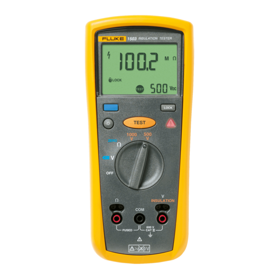
Introduction The Fluke Models 1503, 1507 and 1508 are battery-powered insulation testers (hereafter, Tester or UUT). These Testers meet CAT IV IEC 61010 standards. The IEC 61010 standard defines four measurement categories (CAT I to IV) based on the magnitude of danger from transient impulses. -
Page 10: Contacting Fluke
To contact Fluke, call: 1-888-993-5853 in USA +81-3-3434-0181 in Japan 1-800-363-5853 in Canada +65-738-5655 in Singapore +31-402-678-200 in Europe +1-425-446-5500 from anywhere in the world Visit Fluke's web site at: www.fluke.com Register your Meter at: register.fluke.com Downloaded from Elcodis.com electronic components distributor... -
Page 11: General Specifications
Insulation Testers General Specifications General Specifications Maximum Voltage Applied to any Terminal ... 600 V ac rms or dc Storage Temperature........-40 °C to 60 °C (-40 °F to 140 °F) Operating Temperature ........-20 °C to 55 °C (-4 °F to 131 °F) Temperature Coefficient ........ -
Page 12: Electrical Specifications
150X Series Calibration Manual Electrical Specifications AC/DC Voltage Measurement Accuracy 50 Hz to 400 Hz Range Resolution ± (% of Rdg + Digits) 600.0 V 0.1 V + (2 % + 3) Input Impedance ..........3 MΩ (nominal), <100 pF Common Mode Rejection Ratio (1 kΩ... -
Page 13: Models 1507 And 1508
Insulation Testers Electrical Specifications Models 1507 and 1508 Accuracy Output Voltage Display Range Resolution Test Current ± (% of Rdg + Digits) 0.01 to 20.00 MΩ 0.01 MΩ 50 V ± (3 % + 5) 1 mA @ 50 kΩ (0 % to + 20 %) 20.0 to 50.0 MΩ... -
Page 14: Insulation Resistance Maximum And Minimum Display Values (Models 1503 And 1507)
150X Series Calibration Manual The following tables can be used to determine the maximum or minimum display values considering maximum instrument operating error per EN61557-1, 5.2.4. Insulation Resistance Maximum and Minimum Display Values (Models 1503 and 1507) 50 V 100 V 250 V 500 V 1000 V... -
Page 15: Earth-Bond Resistance Maximum Display Values (Models 1503 And 1507)
Insulation Testers Basic Maintenance Insulation Resistance Maximum and Minimum Display Values (cont.) 50 V 100 V 250 V 500 V 1000 V Minimum Minimum Minimum Minimum Minimum Limit Limit Limit Limit Limit Display Display Display Display Display Value Value Value Value Value Value... -
Page 16: Testing The Batteries
150X Series Calibration Manual Testing the Batteries XWWarning To avoid electrical shock or personal injury, replace the batteries as soon as the battery indicator (B) appears. A weak battery can cause false readings. The Meter continuously monitors battery voltage. If the low battery icon (B) appears on the display, there is minimal battery life left. -
Page 17: Testing The Display
Min interrupt rating 10000 A ecz15f.eps Fuse, Fast, 315 mA, 1000 V, Min Interrupt Rating 10000 A Fluke PN 2279339 Battery, 1.5 V AA Alkaline, NEDA 15A, IEC LR6 Fluke PN 376756 Figure 1. Replacing the Fuse and Batteries Testing the Display Press and hold the blue key, and simultaneously turn the UUT on. -
Page 18: Keypad Test
150X Series Calibration Manual Keypad Test The keypad consists of six keys located above the rotary switch. 1. To test the keypad, turn the rotary switch to and momentarily press each of the six keys. Each press of an operational key will cause the Meter to beep. No beep in response to a key press indicates a defective keypad. -
Page 19: Removing The Boot
Insulation Testers Disassembling and Reassembling the Meter Removing the Boot The standard Meter comes equipped with a snug-fitting yellow rubber boot. The boot helps protect the Meter from rough handling and is normally left on the Meter. The first step in disassembling the Meter is to remove the boot. Use the following procedure to remove the boot: 1. -
Page 20: Opening The Bottom Case
150X Series Calibration Manual Opening the Bottom Case With the battery door removed, the next step in disassembling the Meter is to remove the bottom case. Use the following procedure to remove the bottom case: Note When removing the back cover, it is not necessary to remove the fuse or the batteries. -
Page 21: Removing The Lcd
Insulation Testers Disassembling and Reassembling the Meter 3. With one hand over the PCA, roll the top case over (face up) and lift it away from the PCA. Note Two red and one black plastic shields are used to isolate the user from the input terminals. -
Page 22: Replacing The Lcd
150X Series Calibration Manual PCA Screws Fuse Light-dispersing Back Panel Glass LCD Display Elastomeric Strip Gray Plastic Bezel ecz21f.eps Figure 5. Accessing the LCD Replacing the LCD The LCD assembly consists of four pieces as shown in Figure 5: • Translucent light-dispersing back panel •... -
Page 23: Reassembling The Meter
Insulation Testers Disassembling and Reassembling the Meter 7. While holding the LCD assembly (face down) in one hand, position the PCA (fuse side up) over the bezel; match the guide holes in the PCA with the plastic guide pins on the bezel and the translucent light dispersing back panel. After the LCD assembly is in position, lock it in place by pressing (below the display) the bezel against the PCA;... -
Page 24: Required Tools And Equipment
Table 2. Required Equipment Equipment Required Characteristics Recommended Model Calibrator AC Voltage Range: 0 - 600 V Fluke 9100 w/135 option Accuracy: +/- 0.5% Frequency Range: 50 Hz - 400 Hz Accuracy: +/-3% DC Voltage: 0 - 600 V Accuracy: +/-0.5% Ohms Range: 0 - 20 kΩ... -
Page 25: Performance Tests
Meter (UUT) and its performance level. The performance test is recommended as an acceptance test for incoming inspection and as a calibration procedure for periodically ensuring the accuracy of the Meter. Fluke recommends running the performance test at least once a year. -
Page 26: Testing The Insulation Function
5500A, 5520A or other standard calibrator for the insulation tests. WCaution To avoid damage to the Fluke 9100 make sure to select the insulation test function prior to pushing the UUT T key. Insulation Resistance Accuracy Tests To test the insulation resistance accuracy complete the test steps in Table 4, using the following procedure. -
Page 27: Full-Scale Insulation Resistance Accuracy Test, 1000 V Range (Models 1507 And 1508)
Insulation Testers Performance Tests Table 4. Insulation Resistance Accuracy Test Insulation Display Reading Limits Step Applied Display Units Voltage Range 1503 1507/1508 1000 V 1.9 GΩ 1862 to 1938 1000 V 1 MΩ 0.5 to 1.5 0.5 to 1.5 1000 V 49 MΩ... -
Page 28: Of Full Scale, Insulation Resistance Accuracy Test, 50 V Range (Models 1507 And 1508)
150X Series Calibration Manual Calibrator DANGER HIGH VOLTAGE OUTPUT 15Vpk Ω 1500Vpk Ñ Mode 15Vpk 50 k ecz16f.eps Figure 6. 9-GΩ Resistor Verification 5 % of Full Scale, Insulation Resistance Accuracy Test, 50 V Range (Models 1507 and 1508) The following test verifies the minimum insulation resistance accuracy, of the 50 V range, using a separate 50-kΩ... -
Page 29: Source Voltage Accuracy Test, "R" Nominal
Insulation Testers Performance Tests Source Voltage Accuracy Test, "R" Nominal Complete the test steps in Table 5 to verify source voltage of the insulation function under load. 1. Connect the test DMM and calibrator in parallel to the UUT INSULATION terminals. -
Page 30: Source Voltage Accuracy Test, Open Circuit
150X Series Calibration Manual Calibrator Test DMM 1507 INSULATION TESTER DANGER HIGH VOLTAGE OUTPUT 15Vpk Ω 1500Vpk Ñ Mode 15Vpk Calibrator HIGH VOLTAGE DANGER OUTPUT 15Vpk Ω 1500Vpk Ñ Mode 15Vpk >1000 mV Test DMM 1507 INSULATION TESTER 80K-6 HV Divider ecz12f.eps Figure 7. -
Page 31: I Nominal Test
Insulation Testers Performance Tests 3. Using the previously determined Meter Voltage Reading Error %, calculate the actual open circuit output voltage for each voltage range. Verify that the calculated value is within the limits shown in Table 6. The formula is UUT Recorded Reading x UUT Voltage Reading Error % + Recorded UUT Display Reading. - Page 32 150X Series Calibration Manual I Nominal Test Test DMM >1000 µA Calibrator 1507 INSULATION TESTER DANGER HIGH VOLTAGE OUTPUT 15Vpk Ω 1500Vpk Ñ Mode 15Vpk I Limit Test 1507 INSULATION TESTER Test DMM 50 k ecz13f.eps Figure 8. I Nominal Test/I Limit Test Connection Downloaded from Elcodis.com electronic components distributor...
-
Page 33: I Limit Test
Insulation Testers Performance Tests Table 7. I Nominal Test/Limit Test Step Function Range Applied Load DMM Display Reading Insulation 1000 V 1 MΩ Insulation 500 V 500 kΩ >1000 Insulation 250 V 250 kΩ Insulation 100 V 100 kΩ (1507/1508) Remove the Calibrator and apply a separate 50 kΩ... -
Page 34: 2-Ohm Output Current Test
150X Series Calibration Manual Table 8. Earth Bond Resistance Tests Display Reading Step Meter Range Applied Display Units Low Limit High Limit 2000 Ω 810.0 Ω Ω 2000 Ω 990.0 Ω Ω 1008 20.00 KΩ 18.0 kΩ kΩ 17.70 18.30 Remove calibrator and apply a separate 2 Ω... -
Page 35: Open Circuit Voltage Test
Insulation Testers Calibration Adjustment Open Circuit Voltage Test The following test confirms that the open circuit voltage is within limits. 1. Connect a DMM directly to the UUT Ω terminals observing correct polarity. 2. Set the DMM rotary function switch to the VDC function. 3. -
Page 36: Restoring The Default Password
150X Series Calibration Manual 6. Press H to change the password. The Meter displays ---- if the old password is correct. If the password is not correct, the Meter emits a double beep, displays ---- and the four key password must be entered again. Repeat step 4. 7. -
Page 37: Keys Used In The Calibration Steps
Insulation Testers Keys Used in the Calibration Steps Keys Used in the Calibration Steps The Meter keys behave as follows when performing the calibration adjustment procedure. T stores the calibration value and advance to the next step. H ignores the calibration value and advance to the next step. This key is also used to exit calibration function after the calibration adjustment sequence is complete. - Page 38 150X Series Calibration Manual Table 9. Calibration Adjustment Steps Switch Position Input Terminal Adjustment Step Input Value C-01 0m A, 0 Hz C-02 15u A, 0 Hz 1000 V Insulation C-03 0.18 mA, 0 Hz C-04 1.8 mA, 0 Hz + : COM C-05 0.5 mA, 0 Hz...
-
Page 39: Service And Parts
User service is limited to replacing parts. Table 10 identifies the replacement parts used by all models, Tables 11, 12, and 13 identify the replacement parts unique to each model. Figure 10 shows the location of each part. To order replacement parts refer to Contacting Fluke earlier in this manual. MP32 MP18... - Page 40 FLUKE-15X7-8012,TILT STAND 2278143 MP18 FLUKE-15X7-8014,HOLSTER 2278162 MP19 FLUKE-15X7-8016,BATTERY CONTACT,NEG 2281317 MP20 FLUKE-15X7-8017,BATTERY CONTACT,POS 2281321 MP21 LCD,TN,3.0V,TRANSFLECTIVE,1/4-DUTY,1/3-BIAS 2156884 MP22-24 FLUKE 89-4-8012 ,BATTERY CONTACT, DUAL 666435 MP40-43 BATTERY,PRIMARY,MNO2- 376756 ZN,1.5V,2.24AH,15A,LR6,ALKALINE,AA,14X50MM,BUL H26-29 SCREW,5-14,.750,PAN,PHILLIPS,STEEL,BLK 832246 CHROMATE,THREAD FORMING H30-32 SCREW,4-14,.312,PAN,PHILLIPS,STEEL,ZINC- 642931 CLEAR,THD FORM,#3 HEAD MP32...
- Page 41 MP48 1670652 ALLIGATOR CLIP,600/1000V,2MM JACK,BLACK MP36 2416024 1508 USERS MANUAL (Chinese and English) Table 12. 1507 Specific Parts Ref Des Description 2282433 FLUKE-1507-8004-01,CASE TOP, PAD XFER 2282491 FLUKE-1507-8005-02,BRACKET,MASK,PAD XFER 2388523 FLUKE-1507-8018-01,KEYPAD 2388561 FLUKE-1507-8007-03,DOOR,ACCESS MP46 2070140 TL224-4201,175-263-011 TEST LEADS RA2S MP47 1958654 021-236-003,ALL.CLIP EX-LARGE RED IEC1010...
- Page 42 150X Series Calibration Manual Downloaded from Elcodis.com electronic components distributor...