Table of Contents
Advertisement
Quick Links
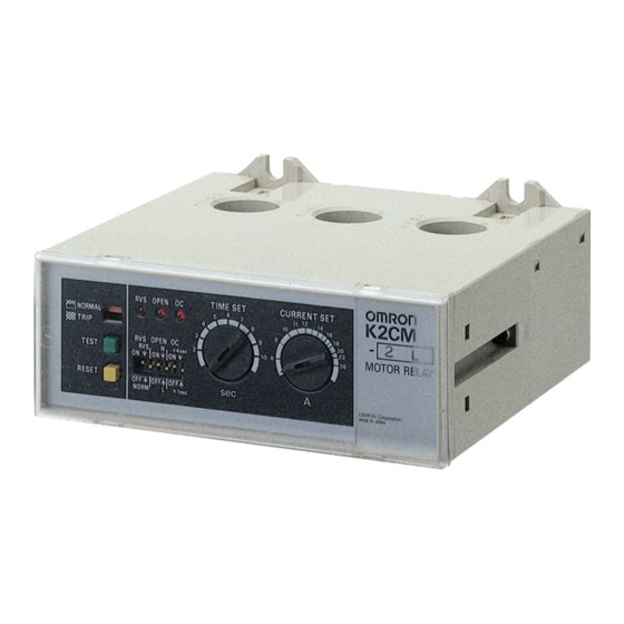
Motor Protective Relay
K2CM
Solid-state Relay Enables Choice of Three
Operating Functions (Overcurrent, Open-
phase, and Reverse-phase)
• Protects 3-phase induction motors and their loads from damage.
• Selection and combination of operating functions from overcur-
rent, open-phase, and reverse-phase.
• Circuit and output relay operation can be checked by just operat-
ing the test button.
• The set time value can be checked easily because operation time
is indicated from the start of operation.
• Space-saving, integrated construction.
Note: If the K2CM is used with an inverter, the operating conditions will
depend on the load wiring length, inverter carrier frequency, basic
frequency, and load conditions. Error will occur in the operating
values of the overload elements. It is recommended to test operation
before using the K2CM.
Model Number Structure
■ Model Number Legend
K2CM-@@@-@@
1
2 3 4
5 6
1. Model
K2CM: Motor relay
2. Mounting style
None: Surface-mounting, integrated type
3. Operating time characteristics
None: Inverse type
Q:
Instantaneous type
4. Supply voltage of control circuit
1:
100/110/120 VAC
2:
200/220/240 VAC
4:
400/440 VAC
Ordering Information
■ List of Models
Voltage Reverse-phase Detection Models
Time specification
Resetting
Current setting range
method
Operating voltage
Manual
200/220/240 VAC
Automatic 200/220/240 VAC
Inverse type
8 to 26 A
20 to 65 A
K2CM-2LV
K2CM-2MV
K2CM-2LAV
K2CM-2MAV
5. Current setting range
LS:
2 to 8 A
L:
8 to 26 A
M:
20 to 65 A
H:
50 to 160 A
6. Operating time
None: ×1 (2 to 10 s)/ ×4 (8 to 40 s) Switchable
7. Resetting method
None: Manual reset
A:
Automatic reset
8. Reverse-phase detection type
None: Current reverse-phase detection
V:
Voltage reverse-phase detection
50 to 160 A
8 to 26 A
K2CM-2HV
K2CM-Q2LV
K2CM-2HAV
K2CM-Q2LAV
CSM_K2CM_DS_E_6_3
Instantaneous type
20 to 65 A
50 to 160 A
K2CM-Q2MV
K2CM-Q2HV
K2CM-Q2MAV
K2CM-Q2HAV
1
Advertisement
Table of Contents

Related Manuals for Omron K2CM Series


Summary of Contents for Omron K2CM Series
- Page 1 Motor Protective Relay K2CM CSM_K2CM_DS_E_6_3 Solid-state Relay Enables Choice of Three Operating Functions (Overcurrent, Open- phase, and Reverse-phase) • Protects 3-phase induction motors and their loads from damage. • Selection and combination of operating functions from overcur- rent, open-phase, and reverse-phase. •...
-
Page 2: Specifications
K2CM Current Reverse-phase Detection Models Time specification Inverse type Instantaneous type Current setting range 2 to 8 A 8 to 26 A 20 to 65 A 50 to 160 A 2 to 8 A 8 to 26 A 20 to 65 A 50 to 160 A Resetting method... - Page 3 K2CM ■ Characteristics At 20 ±20 °C ±5% of operating value, ±10% of operating time Variation due to Overcurrent: ±10% of operating value, ±10% of operating time temperature Open-phase: Reverse-phase: ±10% of operating value, ±10% of operating time fluctuation At 20 ±30 °C ±10% of operating value, ±20% of operating time Overcurrent: ±20% of operating value, ±20% of operating time...
- Page 4 K2CM Connections ■ Voltage Reverse-phase Detection Models Terminal Arrangement Manual Operation Low-voltage Circuit (High- capacity Motor) 200 VAC 50/60Hz Ta Tc Tb U Stop Start Output contacts Control power (SPDT) supply • Perform the external connections by referring to the examples given below. Magnet contactor •...
- Page 5 K2CM ■ Current Reverse-phase Detection Models Terminal Arrangement Manual Operation Low-voltage Circuit (High- capacity Motor) 200 VAC 50/60Hz Stop Start Output contacts Control power (NO and NC) supply • Perform the external connections by referring to the examples given below. Magnet contactor •...
-
Page 6: Output Circuits
K2CM Output Circuits ■ Internal Circuit and Operation Description Inverse and Instantaneous Voltage Reverse-phase Detection Models Types Reset button With the voltage reverse-phase R S T detection models, the circuit Test button As shown on the right, the K2CM section enclosed by in the diagram on the left is configured as detects abnormalities in motor M... - Page 7 (80% or less of the control power supply). ever, special consideration may be required for the detection of inter- nal open-phases in delta-connected motors. Consult your OMRON representative before using this method. When a transformer is con- nected as a load, the harmonics increase at low loads. Therefore, in...
- Page 8 K2CM Nomenclature Trip Indicator In normal operation, only the upper half of the display window is colored orange, whereas when the motor circuit has tripped, the entire display window becomes orange. Current-setting Knob 10 (side) 9 • By operating the setting knob, set the current value to be equal to the rated current of the motor to be used.
- Page 9 K2CM LED Indicators 3. Reverse-phase Setting Switches These switches select the reverse-phase detection function and When the motor circuit trips due to overcurrent, open-phase, or reverse-phase polarity. By selecting the reverse-phase polarity reverse-phase, the respective LED indicator lights (continuously). accordingly, the K2CM can operate normally without changing the The overcurrent indicator also indicates the start of operation.
-
Page 10: Engineering Data
K2CM Engineering Data Overload Operating Time Overload Operating Time Characteristics for Inverse Type Characteristics for Instantaneous Type Time scale multiplying factor (× 4) (× 1) This graph shows the behavior when the current changes from 100% of the current- setting value to the Time scale percentage shown on the horizontal axis. - Page 11 K2CM Dimensions Note: All units are in millimeters unless otherwise indicated. Surface-mounting Models 46.5 11.5 48.5 Six, M3 terminal screws Four, 6-dia. mounting holes or four, M5 mounting-screw holes 52± 80± 33.5 33.5 Three, 20-dia. holes Operating Procedures ■ Operation, Setting, and Indication Based on the current value of the motor to be used, perform the setting of each item of the K2CM Motor Protective Relay.
-
Page 12: Testing Method
K2CM Testing Method ■ Current Reverse-phase Detection Models 200 V 50/60 Hz (3-phase) The operating characteristics listed in the table below are tested using the circuit shown on the right. Decide the number of conductor 100 VAC passes through the holes of the current transformer in accordance with the operating current range of the Motor Protective Relay and by 50/60Hz referring to the current setting method described under Operation, Setting, and Indication. - Page 13 K2CM ■ Voltage Reverse-phase Detection Models The operating characteristics listed in the table below are tested using the circuit shown on the right. Decide the number of conductor 200 V 50/60 Hz passes through the holes of the current transformer in accordance (3-phase) with the operating current range of the Motor Protective Relay and by referring to the current setting method described under Operation,...
-
Page 14: Safety Precautions
SCR control circuits, VVVF inverters, or recti- ON the overcurrent switch. Also, at this time, turn OFF the open- fiers, may cause errors and malfunctions. Consult your OMRON phase switch and reverse-phase switch to prevent unnecessary representative for details. -
Page 15: Daily Inspection
K2CM ■ Maintenance and Inspection Q & A The K2CM Motor Protective Relay offers very stable characteristics. To maintain these characteristics for a long time, the following inspections are recommended. What is the VA consumption of the CT section? Daily Inspection The consumption is 0.4 VA/phase max. - Page 16 (a) Exclusive Warranty. Omron’s exclusive warranty is that the Products will be free from defects in materials and workmanship for a period of twelve months from the date of sale by Omron (or such other period expressed in writing by Omron). Omron disclaims all other warranties, express or implied.
- Page 17 Mouser Electronics Authorized Distributor Click to View Pricing, Inventory, Delivery & Lifecycle Information: Omron K2CM-1H K2CM-1HA K2CM-1L K2CM-1LA K2CM-1LS K2CM-1M K2CM-1MA K2CM-2H K2CM-2HA K2CM-2L K2CM-2LA K2CM-2LS K2CM-2M K2CM-2MA K2CM-4H K2CM-4HA K2CM-4L K2CM-4LA K2CM-4M K2CM- 4MA K2CM-Q1H K2CM-Q1HA K2CM-Q1L K2CM-Q1LA K2CM-Q1LS K2CM-Q1M K2CM-Q1MA K2CM-Q2H...