Table of Contents
Advertisement
Quick Links
Advertisement
Table of Contents

Related Manuals for Clavia nord C1


Summary of Contents for Clavia nord C1
- Page 1 SERVICE MANUAL...
-
Page 2: Table Of Contents
Running the test program ............4 Error Codes ................6 Hardware ..................7 Hardware structure ..............7 Opening the synth............... 8 Hardware versions..............10 Software ..................10 Spare Parts................. 11 Clavia DMI Service manual Nord C1 Combo Organ rev. 1.0 Page 1... - Page 3 The Nord C1 Combo Organ Service manual is arranged to help our service centers in the best way possible. However the Nord C1 Combo Organ user manual is a very useful guide, use it as a reference in addition to this service manual. If you have access to internet you’ll find the user manual available for download and also a lot of useful...
-
Page 4: Overview
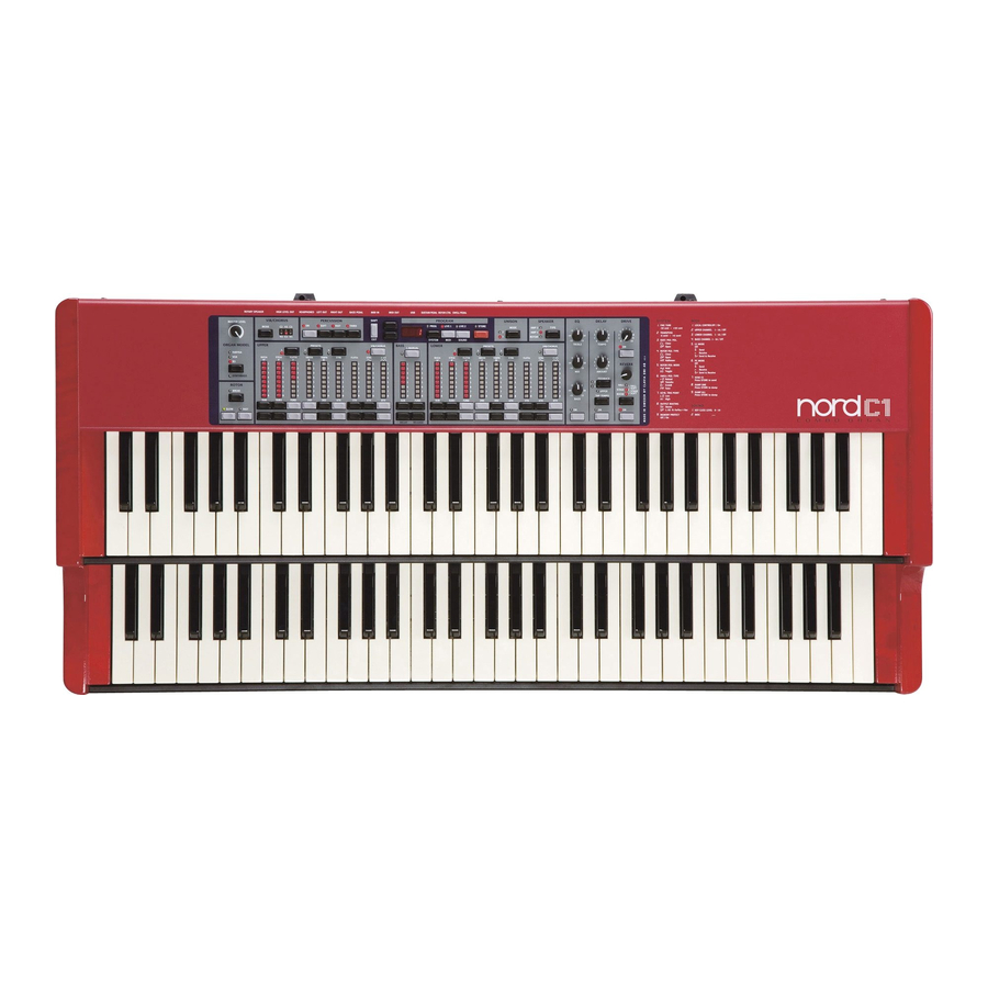
The Nord C1 Combo Organ is available In one version. - 2 x 61 note Keyboard version Internal memory The internal sound memory of Nord C1 consists of 126 program locations. In addition there are two live buffer memories. Fuse ratings Voltage... -
Page 5: Test Program
Test program Running the test program The Nord C1 test program is stored both in Flash and in the BootPROM position U32. Test program version is shown in the display when the test program is initiated. In order to trace a hardware error easier, each Nord synthesizer has a test program. - Page 6 Checksum Only used in production 2.CS Erase Flash Will set all data in Flash to “1” 3.EF Clear EEPROM Will set all data in EEPROM to “0” 4.CL Clavia DMI Service manual Nord C1 Combo Organ rev. 1.0 Page 5...
-
Page 7: Error Codes
When an error is detected within the test program it will be presented either as “Err” Or by the corresponding chip id flashing in the display, e.g “ ” Clavia DMI Service manual Nord C1 Combo Organ rev. 1.0 Page 6... -
Page 8: Hardware
(25551) connectors P1-P4 (22670) Panel Board On the panel board you will find all control functions of the Nord C1. This panel also holds the LED he panel board is connected to the main board with a 26 pole (3x20780) connector P1 (22520). -
Page 9: Opening The Synth
4. Disconnect the 26 pole ribbon cable (23830) to the mainboard. Removing the Panelboard 1. Pull off the knobs (22900). 2. Disconnect the 26 pole ribbon cable (23830). 3. Remove the 12 screws (40262) holding the panelboard. Clavia DMI Service manual Nord C1 Combo Organ rev. 1.0 Page 8... - Page 10 5. Disconnect the 10 pole ribbon cable to the powerboard. (23880) 6. Disconnect the 10 pole rotary spkr cable (22093). Disconnect the 4 keyboard cables (P1-P2 22290 P3-P4 24100) Clavia DMI Service manual Nord C1 Combo Organ rev. 1.0 Page 9...
-
Page 11: Hardware Versions
For more information on how to update the OS Visit www.clavia.se there you can find the latest Software packages. Current OS version is shown in the display when you power on the unit. Clavia DMI Service manual Nord C1 Combo Organ rev. 1.0 Page 10... -
Page 12: Spare Parts
40298 Angle bracket NC1O, short 40239 U-channel 40299 U-channel NC1O, long 40280 Wood panel NC1O, left 40281 Wood panel NC1O, right 50288 Bumper, Nord Stage 22093 Cable Rotary spkr complete Clavia DMI Service manual Nord C1 Combo Organ rev. 1.0 Page 11... - Page 13 23190 USB circuit NMG2/NS 23960 220uF/25V Ellyt axiell 25820 Regulator step-up 40180 Spacer 2mm Nylon 25351 Crystal oscillator 16,6666 MHz 23270 Crystal oscillator 56,620363 Mhz 23060 crystal 6 Mhz SMD Clavia DMI Service manual Nord C1 Combo Organ rev. 1.0 Page 12...