
Related Manuals for Rinnai CAH Series


Summary of Contents for Rinnai CAH Series
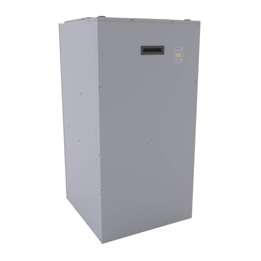
- Page 2 Canadian Air Handler Installation and Operation Manual...
- Page 3 Thank you for purchasing Rinnai’s Hydronic Air Handler. Before installing and operating the air handler, be sure to read these instructions completely • It is recommended that a trained and and carefully to familiarize yourself with the qualified professional who has attended a features and functionality.
- Page 4 • It is recommended that a trained and qualified professional who has attended a Rinnai installation training class complete CAUTION your installation. • Read these installation instructions carefully Indicates a potentially hazardous situation...
-
Page 5: Electrical Connections
It is the responsibility of the installer to follow all The hydronic air handler is designed to work national codes, standards and local ordinances, with Rinnai tankless water heaters and boilers in addition to the instructions in this manual. The (models listed below) to deliver a wide variety... - Page 6 • Do not store components outdoors. Series • If transported or stored at temperatures CAH Series below 32°F (0°C), the components must be warmed up to 60°F (15°C) before the start of assembly. • All components must be stored in the original packaging.
- Page 7 Hydronic Coil Water Inlet Water Outlet Hot Water From Water Cold Water Returning to Heater/Boiler into Air Water Heater/Boiler Handler Control Panel 120V Terminal 24V Thermostat Cable Knockout Access Port (available on left or right side) ECM Blower Motor 120V Power Supply and Housing Knockout Access Port (available on left or right...
- Page 8 A-Coil and Ductwork (Field-Supplied) Refrigerant Lines (Field- Supplied) to Condensing Unit Water Inlet/Outlet From Water Heater/Boiler (they are co-linear and cannot both be seen on the side profile) Air Handler Canadian Air Handler Installation and Operation Manual...
- Page 9 Example Vertical (Upflow with Side Return) Configuration SUPPLY (Air Flows Out) Supply Rinnai Tankless Ductwork Water Heater or Boiler Thermostat A call for heat from the thermostat activates the air handler Cold Water Inlet Water Outlet RETURN Hot Water From...
- Page 10 1 Reference tables in sections 3.7.2 for specific BTU output. * Refer to P9-11 listings for latest information and results. Rinnai products are continually being updated and improved; therefore, specifications are subject to change without prior notice. Canadian Air Handler Installation and Operation...
- Page 11 Values shown in following tables may vary depending on the static pressure of the duct system. Entering Water 100% Engine Temperature (°F) (800CFM) (1200 CFM) (1600 CFM) SENSEI 26,600 34,700 41,400 I-Series 28,500 38,400 44,600 SENSEI 37,500 49,100 57,400 I-Series 39,100 54,900 64,100...
- Page 12 Copper NOTE Diameter • All values have Fitting 3/4 in. 1 in. been normalized to 90 Degree Elbow 0.75 3/4 in. copper pipe 45 Degree Elbow 0.75 as a baseline. • It is not Straight Through Tee 0.135 recommended to Side Port Tee 1.35 use ½...
- Page 13 Measurements: in. (mm) 18.5 (470) 14.38 (365) 17 (432) 39.25 (997) 20.5 (521) 21.38 (543) Canadian Air Handler Installation and Operation Manual...
- Page 14 REU-OPU3 Normally Closed (NC) switch that connects to the PC Board in the Rinnai tankless water heater or boiler. Allows the tankless water heater or boiler to give priority to domestic hot water by shutting off the air handler when necessary. When used with a hydronic air handler, the switch gives priority to domestic hot water.
- Page 15 Carefully unpack the air handler. If the unit is damaged, contact your local dealer/distributor. Do When choosing an installation location, you not attempt to use the air handler if it appears must ensure proper clearances will be met; the damaged. installation environment;...
- Page 16 • Unsuitable heating system water can cause the formation of scale or sludge, which affects system efficiency. It can also cause corrosion and reduce life of the heat Clearances to combustible exchanger. material is 0 in. to • Never use water that has been treated by a plenum and duct for first 36 in.
- Page 17 I-Series Condensing Boiler Installation • It is recommended that a trained and qualified and Operation Manual for approved glycol professional who has attended a Rinnai manufacturers. installation training class complete your • The air handler and its complementing installation.
- Page 18 • Install ductwork in accordance with NFPA WARNING 90B and any local codes. • Install the conditioned air plenum, ducts Before installing or servicing the air handler, and air filters (not provided) in accordance turn off power to unit. There may be more with NFPA 90B Standard for the than one disconnect switch.
- Page 19 • Use copper conductors only. • All field wiring must be done in accordance with National Electrical Code, applicable requirements of UL and local codes, where applicable. WARNING • Electrical wiring, disconnect means and over-current protection are to be supplied by Electrical Shock: the installer.
- Page 20 Another alternative is to install an expansion plumbing location: compensator fitting capable of absorbing the • 5.9.1 Rinnai Tankless Water Heater and movement. Air Handler Piping Diagram Hydraulic Resistance of Fittings, Valves, and •...
- Page 21 IMPORTANT Vertical (downflow with bottom, back, or side return) Read section “4. Installation Preparation” before starting installation steps. RETURN Air flows in through bottom, back, or side (left or right side) Refer to the previous section (section “4. Installation Preparation”) for more information SUPPLY (Upflow) on location and configuration requirements.
- Page 22 Do not position the air handler on its front or back panel. Front Back • Multiple air handlers configured for installation with a single Rinnai tankless water heater or boiler is prohibited. Refer to section “4.7 Electrical Requirements” for complete electrical requirements. NOTE Electrical cables go through the knockout holes on the left or right side of the cabinet.
- Page 23 Air Handler Thermostat Wiring Block Rinnai Domestic Priority Switch: LOW VOLTAGE/BASSE TENSION Rinnai REU-OPU3 (accessory installed in Rinnai Engine) DH O V/W2 Field Supplied Thermostat Connections to the Air Handler PC Board. Other thermostat wires removed for clarity. 1. Disconnect all power supplies.
- Page 24 The CAH050E model air handler does not have an included circulator pump. If utilizing the air handler with a Rinnai I-Series combi boiler, the accessory pump is not 1. Mount the thermostat approximately 5 ft.
- Page 25 LOW VOLTAGE/BASSE TENSION V/W2 120V Pump Supply 120V Power Supply 24V Thermostat Terminals Wire leads removed for clarity. A single stage or two stage thermostat must be installed with the air handler. Thermostat Field Connections (use depends on the applica- tion) •...
- Page 26 Single Stage Hot Water Heat Only Application Two Stage Hot Water Heat Only Application Air Handler Thermostat Air Handler Thermostat V/W2 V/W2 V/W2 V/W2 NOTE Connect common (C) wire only if required. See thermostat installation instructions for more information. Canadian Air Handler Installation and Operation...
- Page 27 Heat Pump Application with Hot Water Heat Cooling Application with Hot Water Heat Air Handler Thermostat Outdoor Unit Air Handler Thermostat Outdoor Unit V/W2 V/W2 V/W2 V/W2 NOTE Connect common (C) wire only if required. See thermostat installation instructions for more information. Canadian Air Handler Installation and Operation Manual...
- Page 28 Heating Application with I-Series Boiler V/W2 V/W2 I Series Boiler T/T 1 Terminals Canadian Air Handler Installation and Operation...
- Page 29 Hot Water Heat with Rinnai REU-OPU3 Install the Rinnai Tankless Water Heater or Boiler by following the Installation and Operation Manual supplied with the unit. V/W2 V/W2 Water Potability This unit can be installed in hot water domestic loop. The hot water coil is certified to NSF 372.
- Page 30 Installation and Operation Manual. • Water connections to the air handler should follow all state and local plumbing codes. 1. Plumb the water out/supply of the Rinnai Water Inlet Water Outlet tankless water heater or boiler to the inlet (top...
- Page 31 Confer with local building officials before installation. Gas Supply Line Condensation Drain Line as Appropriate Cold Water Supply Line Thermostat Thermostatic Mixing Valve Rinnai Canadian Air Handler Hot Water Outlets See next page for Legend Canadian Air Handler Installation and Operation Manual...
- Page 32 This is not an engineering drawing; it is intended only as a guide and not as a replacement for Optional Low Water professional engineering project drawings. This Cut-Off (LWCO) drawing is not intended to describe a complete system. It is up to the contractor or engineer to Outdoor Reset determine the necessary components and Sensor...
- Page 33 This is not an engineering drawing; it is intended only as a guide and not as a replacement for professional engineering project drawings. This drawing is not intended to describe a complete system. It is up to the contractor or engineer to Optional Low Water determine the necessary components and Cut-Off (LWCO)
- Page 34 Flushing the hot water coil prior to start up is required to remove any residual material from the The following conditions must be met prior to starting installation or manufacturing processes as well the air handler. Refer to outdoor condensing unit as remove any air from the system.
- Page 35 Air Flow Inspection: • For proper cooling operation, the airflow through the indoor coil should be between 350 and 450 CFM per ton of cooling capacity (or 350 – 450 CFM per 12,000 BTU/HR) based on the rating of the outdoor unit. •...
- Page 36 The blower motor is a true variable speed motor designed to deliver constant CFM. Constant CFM is valid, up to 1600cfm, with total static pressure up to 0.7 in. w.c. Constant CFM is valid, up to 1200cfm, with total static pressure up to 1.2 in. w.c. Single Stage Thermostat Single Stage Thermostat •...
-
Page 37: Electrical Shock
• It is recommended that a trained and qualified • Keep the motor free of dust and dirt by professional who has attended a Rinnai cleaning annually. Verify that the wheel turns installation training class perform service to freely. Verify the electrical connections on the the air handler. - Page 38 WHITE BLACK C-R1 PUMP BLACK BLACK INDUCTOR WHITE BLOWER MOTOR (120V) MOTOR ECM 16 PIN CONTROL CONNECTOR BLACK 120V WHITE TRANSFORMER 120-24V 40VA BLACK BLUE YELLOW GREEN WHITE PURPLE THERMOSTAT PINK PURPLE WHITE GREEN BLACK BLACK BLUE YELLOW BLACK BLUE GREY BROWN Canadian Air Handler Installation and Operation...
- Page 39 Canadian Air Handler Installation and Operation Manual...
-
Page 40: Troubleshooting
Verify there no air trapped in the heating loop. Purge the loop if air is present. • Verify Rinnai Engine operation and water temperature. Clean inlet water filter on Rinnai engine. • Verify there are no restrictions in the heating loop. Verify all valves are fully open and functional. - Page 41 FAN MENU The fan menu allows to modify the options related to the comfort fan of the appliance: Parameter Description SOFTWARE SETTINGS CONT FAN Allows you to modify the airflow in Configuration and installer menus allow you to RATIO continuous fan mode. modify both display and operational parameters of HEAT FAN Allows you to modify the airflow in...
- Page 42 COOLING / HP MENU SYSTEM MENU The Cooling / HP menu allows to modify the The system menu allows to modify the following options regarding the behavior with an outdoor parameters: unit. Parameter Description Parameter Description FURNACE This parameter allows to manually AC/HP Allows you to specify the tonnage of MODEL...
- Page 43 Item # Part Number Description Item # Part Number Description 609000064 FLOOR PANEL 609000075 SCREW TEKS WSH #8-18 X 1/2 BLOWER SEPARATOR 605000046 CAPACITANCE 609000065 ASSEMBLY LEG AND BELLY BAND 609000076 609000066 RIGHT PANEL ASSEMBLY ASSEMBLY 609000067 BACK PANEL ASSEMBLY 607000035 PUMP KIT 609000068...