Advertisement
Quick Links
SERVICE MANUAL
CONTENTS
PANEL LAYOUT ........................................................................................ 3
SPECIFICATIONS ..................................................................................... 4
CIRCUIT BOARD LAYOUT .......................................................................6
WIRING & BLOCK DIAGRAM ..................................................................7
DISASSEMBLY PROCEDURE ................................................................. 8
CIRCUIT BOARDS ................................................................................. 11
LSI PIN DESCRIPTION ......................................................................... 13
IC BLOCK DIAGRAM ............................................................................15
TEST PROGRAM ................................................................................... 18
INITIALIZE ...............................................................................................26
ERROR MESSAGES ..............................................................................28
CONNECTING CABLES ........................................................................ 29
MIDI IMPLEMENTATION CHART ......................................................... 30
PARTS LIST
OVERALL CIRCUIT DIAGRAM
SY
011451
HAMAMATSU,JAPAN
0.32K-5351 I Printed in Japan'98.12
Advertisement

Related Manuals for Yamaha MU128


Summary of Contents for Yamaha MU128
- Page 1 SERVICE MANUAL CONTENTS PANEL LAYOUT ..................3 SPECIFICATIONS ..................4 CIRCUIT BOARD LAYOUT ...............6 WIRING & BLOCK DIAGRAM ..............7 DISASSEMBLY PROCEDURE ..............8 CIRCUIT BOARDS ................. 11 LSI PIN DESCRIPTION ................. 13 IC BLOCK DIAGRAM ................15 TEST PROGRAM ................... 18 INITIALIZE ....................26 ERROR MESSAGES ................28 CONNECTING CABLES ................
- Page 2 IMPORTANT NOTICE This manual has been provided for the use of authorized Yamaha Retailers and their service personnel. It has been assumed that basic service procedures inherent to the industry, and more specifically Yamaha Products, are already known and understood by the users, and have therefore not been restated.
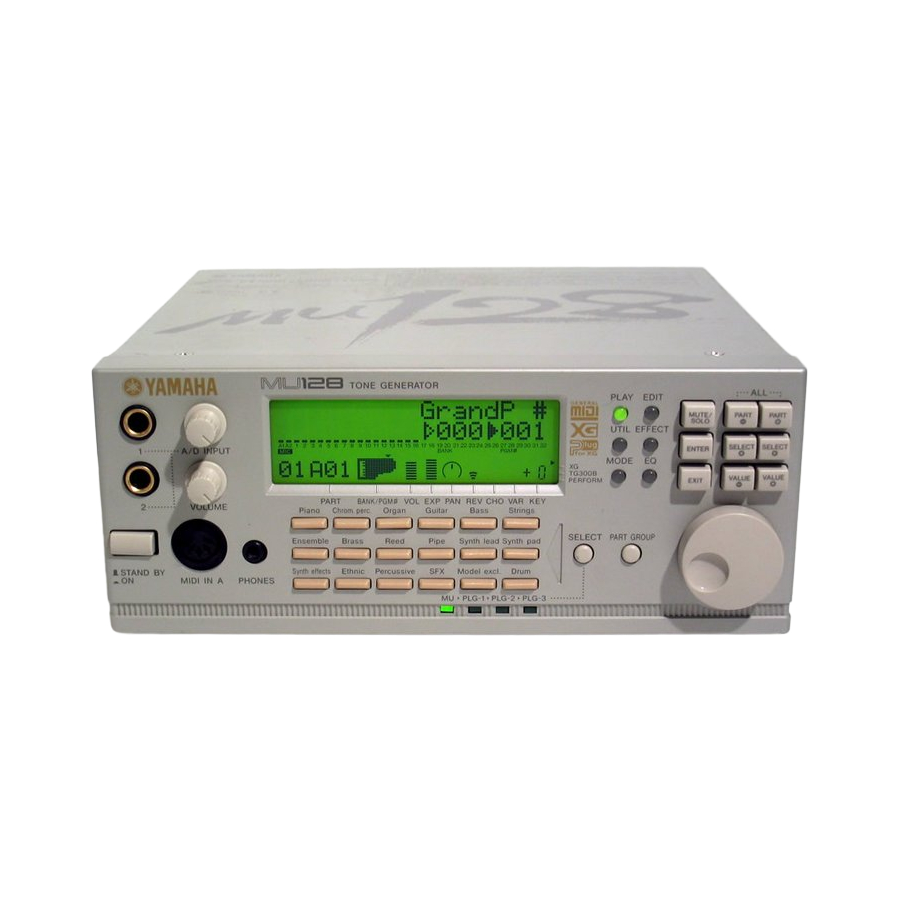
- Page 3 MU128 Front Panel 1. A/D INPUT1,2 jacks A. UTIL (UTILITY) button 2. A/D INPUT VOLUME control B. EFFECT button 3. VOLUME control C. EQ button 4. STAND BY/ON switch (Power Switch) D. MUTE/SOLO button 5. MIDI IN A (front panel) E.
- Page 4 MU128 1. FUNCTION Tone generation Method AWM2 (Advanced Wave Memory 2) Maximum Simultaneous Polyphony 128-note Sound Module Modes XG, TG300B and Performance Multi-timbral Capacity 64-part (on 64 MIDI channels; with dynamic Voice allocation) Effects Seven sections of multi-effects: Reverb(12 Types), Chorus(14...
- Page 5 Rear panel:INPUT L, R jacks (Left,Right), OUTPUT L, R jacks (Left,Right), DC IN jack, TO HOST terminal, HOST SELECT switch, MIDI IN-A/B, MIDI OUT, and MIDI THRU terminals, XG Plug-in board expansion bay 6. POWER SUPPLY Yamaha PA-6 AC Adaptor (included) 7. DIMENSIONS (W 219.5(W)X229.5(D)X91.1(H)[mm] (8-5/8"X9"X3-1/2") 8.
- Page 6 MU128 l Front View (Front) l Bottom View CN10 CN12 CN11 CN13 (Rear) 2NC-V248430...
- Page 7 MU128 MU128 MU128 MU128 MU128 28C99-8812612 7 7 7 7 7...
- Page 8 MU128 MU128 MU128 MU128 MU128 LEDSW1 Circuit Board and LEDSW2 Circuit Board and LCD and RE Circuit Board Bottom Assembly Remove the bottom assembly. (See Procedure 1.) Remove the four (4) screws marked [80A]. The Remove the four (4) screws marked [60], the two When assembling the bottom assembly, Remove the two (2) screws marked [30].
- Page 9 Also be careful not to touch any parts or connectors of the board. 4. Insert the board along the guide rails about two-thirds of the way inside the MU128, with the connector side face down and toward you (as shown below). Make sure to insert it slowly and gently, keeping the edges of the board inside the proper guide rails, as shown in the illustration.
- Page 10 MU128 Carefully plug in the cable connector to the XG Plug-in connector as shown below, matching the two notches on the cable connector with the sockets on the board. Firmly press the connectors together until they lock. 5. Slowly and gently insert the rest of the XG Plug-in board into the expansion bay.
- Page 11 MU128 MU128 MU128 MU128 MU128 • DM Circuit Board MIDI OUTPUT INPUT THRU IN-A IN-B HOST SELECT TO HOST DC-IN CN13 : CN2 : to Power SW Assembly to PMD-CN1 CN9 : CN11 : to LEDSW1-CN8 to PMD-CN2 to LEDSW1-CN10...
- Page 12 MU128 MU128 MU128 MU128 MU128 • LEDSW1 Circuit Board • RE Circuit Board to DM-CN9 MUTE/ PART PART PLAY EDIT SOLO to DM-CN6 SELECT SELECT UTIL EFECT ENTER VALUE VALUE MODE EXIT (Dial) Component side Pattern side to DM-CN9 SELECT PART GROUP •...
- Page 13 MU128 HD6437043E00F (XS936A00) CPU = = = = NAME FUNCTION NAME FUNCTION /WRHH HH write PE14 Port E Data bus /WRHL PA21 Flash/WE write check (RY/BY) LCD, SW, LED Data control (DB7) PE15 Power supply Ground Data bus Ground Address bus...
- Page 14 MU128 = = = = TC203C760HF-002 (XS725A00) SWP30B (AW M Tone Generator coped with MEG) Standard W ave Processor NAME FUN CTION NAME FUN CTION (Gr ound) (Gr ound) HMD0 HMD1 HMD2 HMD3 HMD4 Address bus of internal register HMD5...
- Page 15 MU128 = m m m m PD63200GS-E1 (XP867A00) DAC (Digital to Analog Converter) NAME FUNCTION NAME FUNCTION 4/8FS 4/8 Fs selection R. REF Channel R voltage reference D. GND Digital ground L. REF Channel L voltage reference 16/8 BIT 16 bit/8 bit selection L.
- Page 16 MU128...
- Page 17 MU128...
- Page 18 The battery voltage is checked by the A/D of the CPU (IC 21). Make sure that the voltage is in the range from 2.9 The tests shown below need not be conducted as to 3.4 V. part of the inspection of MU128. Displaying the test result 21 PB1 RAM 02 BATTERY...
- Page 19 MU128 02 BATTERY Make that the dial is working properly. Slowly turn the dial clockwise until a value of 10 is obtained for "00" on the LCD. When the value 10 is obtained, the next item illustrated below will appear.
- Page 20 MU128 9. MIDI 3 B 12. TO HOST TX/RX MIDI IN B connector Use a MIDI cable and connect the to the MIDI OUT connector. Then perform the test. 12 TO HOST Before starting the test, select MIDI under HOST SELECT.
- Page 21 MU128 1 kHz OUTPUT (R) SOUND When A/D INPUT VOLUME is set at maximum, make su re tha t the spec ified value s s hown bel ow are obtained for OUTPUT (L) and (R). 15 OUTPUT R 1 kHz...
- Page 22 MU128 Distortion factor 0.25 % or less Ending the test When A/D INPUT VOLUME is set at minimum, make Press the [ENTER] button. You will then go to the sure that the specified value shown below is obtained next test.
- Page 23 (Details) The signal input into A/D INPUT is output from the 25. PB2 RAM CN5-MEL OUT of MU128 and a request for the audible signal is made to the PB. The sound source 25 PB2 RAM PB then outputs a 1 kHz sine wave from MEL OUT.
- Page 24 The signal input into A/D INPUT is output from the A request for the board name and version is sent from CN1-MEL OUT of MU128 and a request for the audible signal is made to the PB. the MU to the PB through the...
- Page 25 MU128 2. Testing the sound source PB (PLG100-VL, DX, etc) Make sure that the sound source section and the MEL OUT are functioning properly. 3. Testing the effect PB (PLG100-VH) Make sure that the effect section and the MEL IN/OUT are functioning properly.
- Page 26 When the operation is completed. The MU128 will then return to the Initialize menu 3. To cancel the operation, press the [EXIT] button. The MU128 will then returns to the Initialize menu. Since the Initialize functions replace existing data, you should save any and all important settings to a data storage device or YAMAHA MDF3 before executing these functions.
- Page 27 1 Fact Set (Factory Settings) This restores the original factory settings, including Multi, Performance, Effect, Equalizer and System Setup, of the MU128. 2 XG Init (XG Initialize) (Its parameter will be available when Sound Module mode XG is currently selected.) 3 GM Init (GM Initialize) (Its parameter will be available when Sound Module mode TG300B is currently selected.)
- Page 28 A data error resulted during reception of MIDI massages. Try transmitting the data again, or turn the MU128 off and back on again. MIDI Buffer Full! Too mach MIDI data is being received by the MU128 at one time. Reduce the amount of data being sent to the MU128. No Parameter The selected parameter cannot be displayed with the show MIDI Data function.
- Page 29 MU128 Connecting to an Apple Macintosh Serise Computer Apple Macintosh peripheral cable (M0197). Maximum length 2 meters. Connecting to an IBM-PC/AT Serise Computer PC-1 8-pin MINI DIN to D-SUB 25-pin cable. If your PC-1 type computer has a 9-pin serial port, use the PC-2 type cable.
- Page 30 YAMAHA [ Tone Generator] Date:22-MAY-1998 MU128 Model MU128 MIDI Implementation Chart Version : 1.0 Transmitted Recognized Remarks Function ... Basic Default 1 - 16 Channel Changed 1 - 16 Default Mode Messages 3, 4 (m=1) Altered ************** Note 0 - 127...
- Page 31 MU128 MU128 MU128 MU128 MU128 PARTS LIST CONTENTS OVERALL ASSEMBLY.......... 2 FRONT ASSEMBLY..........4 ELECTRICAL PARTS ........... 6 Note) DESTINATION ABBREVIATIONS J : Japanese model A: Australian model U: U.S. model E: European model C: Canadian model D: German model...
- Page 32 MU128...
- Page 33 MU128 DESCRIPTION REMARKS PART NO. QTY RANK REF NO. OVERALL ASSEMBLY MU128 Front assembly (V248540) Top assembly (V248550) V2500600 Flat Head Tapping Screw-C 3.0X8 MFNI33 VN103500 Lithium Battery CR2032 V2485600 Bottom board assembly (V248560) VF646900 Bind Head Tapping Screw-B 3.0X8 MFNI33...
- Page 34 MU128...
- Page 35 MU128 DESCRIPTION REMARKS PART NO. QTY RANK REF NO. Front assembly MU128 (V248540) V2485700 Front Panel Jack assembly (V248580) V2369800 Circuit Board ADMVR2 V2369000 Circuit Board V2476500 Holder, Jack VC069600 Bind Head Tapping Screw-B 2.6X6 MFZN2Y V3298600 Front Shield V2482700...
- Page 36 MU128 PART NO. DESCRIPTION REMARKS REF NO. QTY RANK ELECTRICL PARTS MU128 V2369700 Circuit Board ADVR1 (XU844B0) V2369800 Circuit Board ADMVR2 (XU844B0) V2271300 Circuit Board (XU845B0) V2369200 Circuit board LEDSW1 (XU844B0) V2369100 Circuit Board LEDSW2 (XU844B0) V2369000 Circuit Board (XU844B0)
- Page 37 MU128 DESCRIPTION REMARKS PART NO. QTY RANK REF NO. VQ686200 Monolithic Ceramic Cap. F 1.0 16V Z UB245100 Monolithic Ceramic Cap. F 0.100 25V Z UB245100 Monolithic Ceramic Cap. F 0.100 25V Z UF037470 Electrolytic Cap. (chip) 47 16V UB245100 Monolithic Ceramic Cap.
- Page 38 MU128 PART NO. DESCRIPTION REMARKS REF NO. QTY RANK UF066470 Electrolytic Cap. (chip) C140 4.7 50V UF066100 Electrolytic Cap. (chip) C141 1 50V UF066100 Electrolytic Cap. (chip) C142 1 50V UB245100 Monolithic Ceramic Cap. C143 F 0.100 25V Z UB245100 -145 Monolithic Ceramic Cap.
- Page 39 MU128 DESCRIPTION REMARKS PART NO. QTY RANK REF NO. VS201100 Diode D1F60 VB493900 Diode MA221 VB493900 Diode MA221 XD657A00 TC74HC14AF-TP1 VN686000 Photo Coupler PC410T VN686000 Photo Coupler PC410T XI299A00 TC74HC4050AF-T1 BUFFER XT442A00 SI-8050S REGULATOR +5V XR682A00 TC7S66F BILATERAL SWITCH XD657A00...
- Page 40 MU128 PART NO. DESCRIPTION REMARKS REF NO. QTY RANK V2330700 Heat Sink PUE 26-30 VG238200 LC Filter PLT2003C VL139800 Chip Solid inductance BLM31A700SPT 70ohm VL139800 Chip Solid inductance BLM31A700SPT 70ohm VR243700 Chip Inductance 56U LEM2520 T 560J VL139800 Chip Solid inductance...
- Page 41 MU128 PART NO. DESCRIPTION REMARKS REF NO. QTY RANK RD257220 Carbon Resistor (chip) 22.0K 0.1 J RD257100 Carbon Resistor (chip) 10.0K 0.1 J RD257100 Carbon Resistor (chip) 10.0K 0.1 J RD257220 Carbon Resistor (chip) 22.0K 0.1 J RD257220 Carbon Resistor (chip) 22.0K 0.1 J...
- Page 42 MU128 PART NO. DESCRIPTION REMARKS REF NO. QTY RANK RD256820 Carbon Resistor (chip) R155 8.2K 0.1 J RD256820 Carbon Resistor (chip) R156 8.2K 0.1 J RD257240 Carbon Resistor (chip) R157 24.0K 0.1 J RD257240 Carbon Resistor (chip) R158 24.0K 0.1 J...
- Page 43 MU128 DESCRIPTION REMARKS PART NO. QTY RANK REF NO. RE044680 Resistor Array RA27 68X4 RE046470 Resistor Array RA28 4.7KX4 RE046470 Resistor Array RA29 4.7KX4 RE047100 Resistor Array RA30 10KX4 RE047100 RA31 Resistor Array 10KX4 RE044680 RA32 Resistor Array 68X4 RE044680...
- Page 44 MU128 28CC1-8812500(1/2) 4 Note: See parts list for details of circuit board component parts. MU128...
- Page 45 MU128 28CC1-8812500(2/2) 1 ADMVR2 : 28CC1-8812502 1 ADVR1 : 28CC1-8812502 1 RE : 28CC1-8812502 1 LED SW1 : 28CC1-8812502 1 Note: See parts list for details of circuit board component parts. PMD : 28CC1-8812502 1 LED SW2 : 28CC1-8812502 1...