Husqvarna DMS 240 Workshop Manual
Hide thumbs
Also See for DMS 240:
- Operator's manual (80 pages) ,
- Price list (48 pages) ,
- Operator's manual (52 pages)
Table of Contents
Advertisement
Advertisement
Table of Contents

Related Manuals for Husqvarna DMS 240


Summary of Contents for Husqvarna DMS 240
- Page 1 Workshop manual DMS 240 HUSQVARNA CONSTRUCTION PRODUCTS...
-
Page 2: Table Of Contents
CONTENTS Page HUSQVARNA DOCUMENTATION 2. COMPONENTS, WORK TIPS DMS 240 DISMANTLING IN BASIC MODULES 4. GEAR HOUSING 5. GEAR HOUSING – SLIP CLUTCH 6. SPINDLE SHAFT 7. GEAR HOUSING – BEARING REPLACEMENT 8. ELECTRICAL SYSTEMS 9. WIRING DIAGRAM – CABLING, 120 V 10. -
Page 3: Documentation
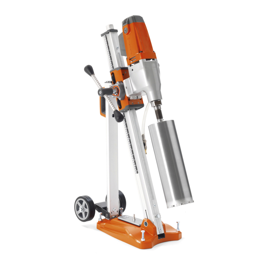
DOCUMENTATION Workshop manual This workshop manual covers virtually all work in the workshop that involves the DMS 240. Some very simple and rather obvious repair work has been omitted. Arrangement – illustrations and text This manual is divided into numbered chapters as well as chapter headings that are specified in bold at the top of each page. - Page 4 COMPONENTS Driller 1. Circuit breaker 2. Carbon brushes 3. Electric motor 4. Gear selector 5. Gear housing 6. Drill spindle 7. Water connection 8. Earth fault breaker (PRCD) 9. Mains cable Stand 10. Tensioning screw 11. Column with measurement scale 12.
-
Page 5: Components, Work Tips
6. Feed screw – low gear 7. Spirit level Work tip The easiest and most convenient way of executing virtually all service work on the DMS 240 is with the machine in a vertical position with the drill spindle facing downwards. Do it yourself A fixture for securing the machine in a vice is easily made using a wood block and a pair of steel plates. -
Page 6: Dismantling In Basic Modules
DISMANTLING BASIC MODULES Basic modules This chapter describes the disassembly of the machine into its basic modules. It only describes the disassembly of the large units. This knowledge forms the basis for performing work at the component level as described later in the workshop manual under the relevant heading. - Page 7 If individual components are replaced/adjusted in the Exxon Mobilgrease 28. gear housing, it is sufficient to move the grease to the Husqvarna art.no: 525 58 35-01. component being fixed. Exception: if an accident has Amount 350 g. led to contamination of the grease with metal shavings, the gear housing must be cleaned and the old grease must be replaced with new.
-
Page 8: Gear Housing
GEAR HOUSING Function The gear housing contains a transmission that reduces the high speed of the electric motor to a lower speed on the spindle shaft. The transmission has two gear positions. Change gear when the motor is off. The transmission is based on three shafts: A. -
Page 9: Gear Housing - Slip Clutch
For removal and adjustment, a special socket is used together with a torque wrench. This can be ordered from Husqvarna, art.no: 523 05 77-02. The secondary shaft with its components are only supplied as a complete spare part, and therefore there is usually no need to dismantle it into its component parts. - Page 10 SPINDLE SHAFT Spindle shaft The complete spindle shaft contains a large number of parts, including axially moving gear wheels for the gear function. The illustration on the left shows the components. The transmission in this machine is rarely the cause of any problems. Incorrect handling of the machine could, however, cause the actual shaft to bend, or damage the tool bracket.
-
Page 11: Spindle Shaft
SPINDLE SHAFT Remove the spindle shaft The steps according to the handbook's opening chapter “Dismantling in basic modules”: – disconnect the motor from the gear housing – divide the gear housing Remove the primary and secondary shaft as per Page 8. 1. -
Page 12: Gear Housing - Bearing Replacement
GEAR HOUSING – BEARING REPLACEMENT Bearings Both bottom bearings are press-fitted in the gear housing and on the shaft. A retaining ring in the gear housing secures the position of the bearings. Radial seals for water distribution to the drill are located at the bottom of the gear housing. - Page 13 GEAR HOUSING – BEARING REPLACEMENT Fitting The mounting of the bearings, spindle shaft and associated components can basically be performed in two ways: – use a hydraulic press to fit the components with a press fit. – use heat/cold to expand/shrink the components and assemble without press forces.
- Page 14 GEAR HOUSING – BEARING REPLACEMENT Fitting the spindle shaft The spindle shaft usually sits with a heavy press fit against the two ball bearings. The problem is that during assembly the bearings are subjected to great axial forces between the outer and inner bearing rings. The shaft must not, under any circumstances, be knocked on site as this will inevitably result in bearing damage.
- Page 15 GEAR HOUSING – BEARING REPLACEMENT Tools Removal The following tools are required for removing the gear housing's bearing: 1. Internal bearing extractor to grip behind the bearings. 2. Use a counter stay device where there is a counterhold. 3. A slide hammer is an alternative to the counter stay device if there is no counterhold available.
-
Page 16: Electrical Systems
ELECTRICAL SYSTEM Electrical system The DMS 240 is fitted with a traditional electric motor, i.e. both stator and rotor have windings and the current is fed to the rotor via carbon brushes to the rotor's collector. The machine's logical and basic electrical design means that checks and servicing can be carried out quickly and easily. - Page 17 Stator Rotor Circuit breaker Stator BLACK BLACK BLACK BROWN BROWN, phase cable 22 kΩ BLUE, neutral cable GREEN/YELLOW, earth cable 100–120 V 0,33 μF Capacitor Gear housing The phase and neutral cables The contact has standardised connector pins for phase, neutral and earth cables.
- Page 18 BLACK BLACK Stator BLACK Rotor Overload Circuit breaker protection Stator BLACK BLACK BLACK BROWN BLUE BROWN Earth fault breaker BLACK 22 kΩ BLUE GREEN/YELLOW 230 V Interference protection 0,33 μF 0,33 μF Gear housing Capacitor Switch, 1 The switch is double pole and opens/closes both connections from/to the network.
-
Page 19: Electrical Cables - Contacts
ELECTRICAL CABLES – CONTACTS Mains cable Supply cables which have been “driven over” or abused are a relatively common cause of interference. If the mains supply does not reach the machine, a broken cable or faulty earth fault breaker is the possible cause. Carry out a visual check of the outside of the cable for damage due to trapping. -
Page 20: Rotor
ROTOR Functional test Starting position – Remove the motor housing from the gear housing, see page 6. Check of rotor A rotor is mainly examined with regard to the condi- tion of the collector and the windings. Short-circuited windings reduce motor power and create a surge of current that overloads the carbon brushes' contact surfaces. -
Page 21: Stator
STATOR Functional test Breaks in the stator winding are detected easily with the following functionality check. In general, short-circuited windings can also be identified, particularly if the short circuit eliminates current in several winding turns. If the short circuit only eliminates a few turns, the measurement is unlikely to record this. A fault like this has hardly any noticeable effect on the performance of the motor either. - Page 22 STATOR Removal Starting position – Remove the motor housing from the gear housing, see page 6. – Remove the connection box from the motor housing and remove the two cables running to the stator. Also disconnect the earth wire from the motor housing. The illustration shows stator 230 V.
-
Page 23: Assembly, Final Testing
ASSEMBLY, FINAL TESTING Fitting The motor housing components are fitted in principle in the reverse order of removal. Note! The earth cable to the gear housing is very close to the fan impeller. If the cable is fitted incorrectly, or is too long, you run the risk that the impeller will abrade the earth wire during operation. -
Page 24: Drill Stand
DRILL STAND Drill stand Maintenance The drill stand requires minimal maintenance. However, it is essen- tial that the stand is kept clean for proper operation. It is particu- larly important that the rack and pinion is free from pollutants and that the set and locking screws are clean and lubricated. The machine bracket must also be thoroughly cleaned and carefully inspected for damage and screw connections. - Page 25 DRILL STAND The illustrations only show the adjustment of the lower roller. The corresponding adjustment must of course also be made for the upper roller. Adjust the roller's abut to the drilling column Use a screwdriver and turn this clockwise to apply the roller to the drilling column.
- Page 26 Mounting machine on drill stand The machine is lowered into place in the machine bracket and locked with two screws, one with a locking lever and one with an Allen screw. A machine that is removed from the stand must always be locked with two screws when reassembling.
-
Page 27: Tools
TOOLS ● = Service stage The tools below can be obtained from Husqvarna. The special tools below are needed for service work to DMS 240 but are not sold by Husqvarna. 523 05 77-02 Counter stay device Socket for hook nut There are a number of manufacturers, e.g.: Kukko (Germany),... - Page 28 www.husqvarnacp.com 115 74 57-26 English 2014-12...