
Related Manuals for Jet JMD-50LPFD


Summary of Contents for Jet JMD-50LPFD
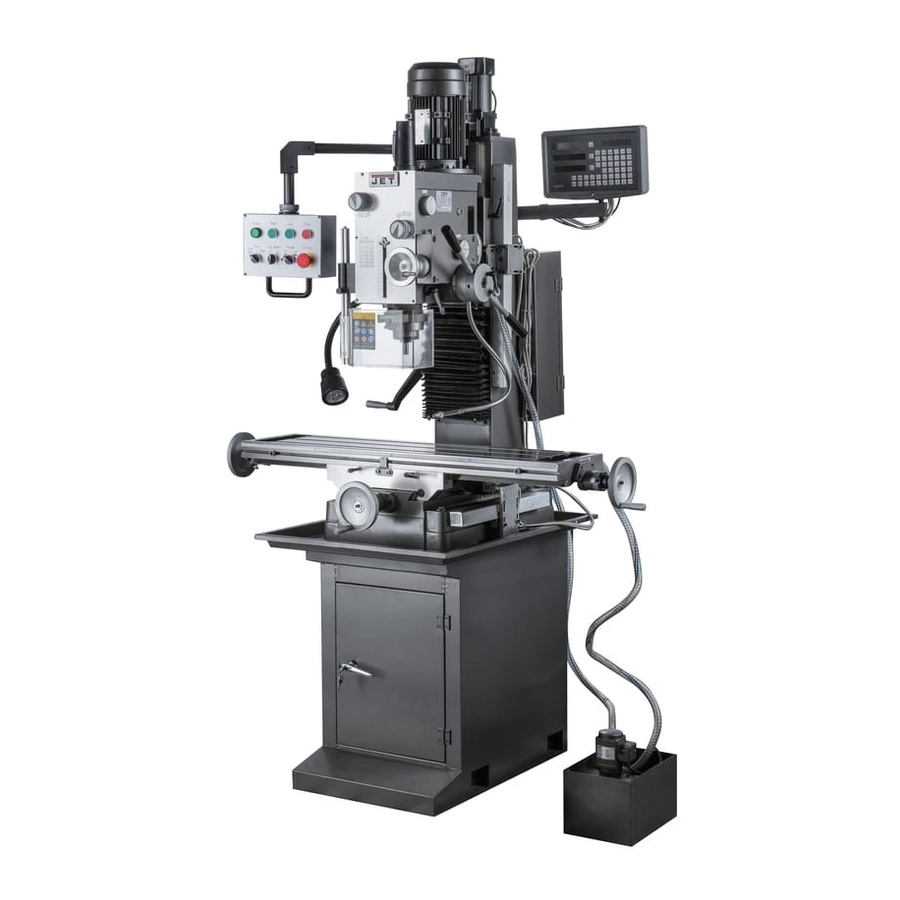
- Page 1 OWNER’S MANUAL GEARED HEAD MILLING & DRILLING MACHINE Model JMD-50LPFD READ ALL INSTRUCTIONS CAREFULLY Keep for future referen...
-
Page 2: Before Operating The Tool
WARNING:FAILURE TO FOLLOW THESE RULES MAY RESULT IN SERIOUS PERSONAL INJURY As with all machinery there are certain hazards involved with operation and use of the machine. Using the machine with respect and caution will considerably lessen the possibility of personal injury. However, if normal safety precautions are overlooked or ignored, personal injury to the operator may result. - Page 3 11.WEAR PROPER APPAREL. No loose clothing , gloves , neckties , rings , bracelets, or other jewelry to get caught in moving parts. Nonslip foot wear is recommended . Wear protective hair covering to contain long hair. 12.ALWAYS WEAR EYE PROTECTION. Refer to ANSIZ87.1 Standard for appropriate recommendations .
- Page 4 5. CAUTION. When practical, use clamps or a vise to secure workpiece to keep the workpiece form rotating while the drill bit or cutting tool. 6. WARNING: FOR Your Own Safety Don’t wear gloves when operating a mill/drill. SPECIFICATION Model JMD-50LPFD Drilling capacity cast iron 45mm mild steel 32mm Face mill capacity...
-
Page 5: Use Of Main Machine Parts
CLEANNING (1) Your machine has been coated with a heavy grease to protect it in shipping. This coating should be completely removed before operating the machine. Commercial degreaser , kerosene or similar solvent may be used to remove the grease form the machine, but avoid getting solvent ob belts or other rubber parts. -
Page 6: Quill Return Spring Adjustment
(1) Before Operation (a) Fill the lubricant (b) In order to keep the accurate precision, the table must be free form dust and oil deposites. (c) Check to see that the tools are correctly set and the workpiece is set firmly. - Page 7 body of the spring housing.) Reset lockscrew make sure point of screw mates the flat on the housing journal. (1) Preparing for Drilling (see fig.2)(Except addition power feed system). Turn of the knob make loose the taper body of worm gear and spring base.
- Page 8 (2)To tighten the longitudinal feed travel of the table for cross feed milling,tighten the two small leaf screw on the front of the table base. (3)Adjustable travel stops are provide on the front of the table for control of cross travel and the desired milling length. TO CHANGE TOOLS (1) Removing Face Mill or Drill Chuck Arbor Loosen the arbor bolt at the top of the spindle shaft approximately 2 turns...
-
Page 9: Troubleshooting Hints
TROUBLE SHOOTING HINTS TROUBLE PROBABLE CAUSE REMEDY Excessive 1.Motor out of balance 1.Balance or replace problem motor. Vibration 2.Bad motor 2.Replace motor Motor stalls 1.Over feeding. 1.Replace feed rate. 2.Dull drill. 2.Sharpen drill and keep sharp. 3.Motor not building up to 3.Replace or repair motor .Check fuses in all running speed. - Page 11 JMD-50LPFD Electrical Model and Specification Function description Supplier code JCH13-20 20/41000 Change-over switch JUCHE JBK5-63VA Transformer AOHENG JCM6-25 Circuit breaker JUCHE NXB-63 C2 Circuit breaker CHNT LA125H-BS542 Emergency stop button MINGER LA125J-11D/206A Start button MINGER Green Indicator light Power on...
- Page 12 Power feed device This machine be equipped with the power feed device see Fig.1. 1.Power feed switch 2.Speed lever 3.Spindle stroke dial 4.Handle 5.Limited screw 6.Locked nut 7.Micro feed dial 8.Locked screw 9.Hand wheel...
-
Page 13: Operation Procedure
OPERATION PROCEDURE Manual feed Turn the power feed switch 1 off, handle 4 with be vertical with the axis of Spindle stroke dial 3, rotate limited screw 5 and be contacted with handle 4, then can be manually feed spindle. When the power feed switch 1 on, make handle 4 vertical , locked limited screw 5, rotate Speed leve 2 to “0”... - Page 15 Code Qty. Name Code Qty. Name 20102 Feed box 20201 Speed lever 20234 Pinion shaft Steel ball 8 20243 Spindle stroke dial Retainer ring 12 20242 Clutch bushing set Spring 20241 Backing pin Screw M6 X 20 Pin 6 X 12 20303 Plate 20247...
- Page 17 Head parts for spindle power feed Qty. Code Name No Qty. Code Name 20010B Head body 6x14 20011B Head body cover 6x28 Retaining ring Ball Retaining ring Spring 20018B Airtight base Retaining ring Airtight ring 5x50 FB45x35x10 Motor M6x8 Screw M8x25 Screw 20107B...
- Page 18 Qty. Code Name Qty. Code Name 20024B Separating ring 6201 Bearing 20133B Oil tight cover Retaining ring 20010C3 Connecting rod Washer M4X12 Screw 20209 Spring Oil seal 20207A Worm shaft FB62X35X10 20307C2 Plate 51101 Bearing 20010C2 (Stents ) 20208B Clutch base M4X10 (Screw) M4x5...
- Page 20 Code Name Code Name 10010 base M5X20 screw 10013 column M8X45 screw 10021 square flange 135LBS (Power feed) 10016 raise and lower base 48 10022 gib strip 10025 gib strip M8X25 screw 10106 screw 10108 movable fixed block 51103 bearing 10109 fixed block support 10104...
- Page 21 Certificate of Inspection Geared Head Milling and Drilling Machine Model JMD-50LPFD Dispatch No.:...
- Page 22 The machine has been qualified and may be permitted to dispatch Head of Inspection Depart__________ Date___________ Director___________ Date___________...
- Page 23 ACCURACY TEST FOR Total 2 MILLING & DRILLING MACHINE Checking items Tolerance Error tested The flatness of worktable surface 0.025 for any tesred length 200 Max 0.08 Squareness of worktable longitudinal movement to 0.04/300 cross movement 0.05 Parallelism of worktable longitudinal movement to the base T-slot Ran-out of spindle hole center line a)Near spindle...
- Page 24 ACCURACY TEST FOR Total 2 MILLING & DRILLING MACHINE Checking items Tolerance Error tested Parallelism of worktable a 0.02 for any 100 movement to worktable surface testing length b 0.0.3 for any 300 testing Max 0.06 Squarencess of spindle a 0.05/300 rotating line to worktable surface a≤90º...
- Page 25 PACKING LIST FOR GEARED HEAD DRILLING & MILLING MACHINE JMD-50LPFD Series No : Dimension : G/W : N/W : Name Spec Model Quantity Remark Milling & drilling machine Draw bar Adapter ISO30/MT3 Taper shank for drilling chunck ISO30/B16 Drilling chuck Φ1~Φ13...