Xerox FaxCentre F110 Service Manual
Hide thumbs
Also See for FaxCentre F110:
- Specifications (2 pages) ,
- Installation manual (4 pages) ,
- User manual (148 pages)
Table of Contents
Advertisement
Quick Links
Advertisement
Chapters
Table of Contents

Related Manuals for Xerox FaxCentre F110


Summary of Contents for Xerox FaxCentre F110
- Page 1 FaxCentre F110 SERVICE MANUAL 12/04...
- Page 2 Xerox service documentation is intended for use by certified, product trained service per- sonnel only. Xerox does not warrant or represent that it will notify or provide to such customer any future change to this documentation. Customer performed service of equipment, or modules, components or parts of such equipment may affect whether Xerox is responsible to fix machine defects under the warranty offered by Xerox with respect to such equipment.
- Page 3 6. General Procedures/Information Section Contents ........................7. Wiring Data Section Contents ........................Also included at the rear of this Service Manual are: - Service Log Sheet - Publication Comment Sheet - Health and Safety Incident Reporting Form FaxCentre F110 12/04...
- Page 4 Introduction Page intentionally blank 12/04 FaxCentre F110...
- Page 5 Safety Precautions IMPORTANT 1. The FaxCentre F110 has been specified as a Class I Unit (earthed/grounded). The Telecom Line potential is isolated from the digital circuitry. To measure on the digital side, the meas- urement equipment should be connected to the same earth (ground). For measurement on the Telecom side, measurement equipment should be unearthed (ungrounded).
- Page 6 Introduction ESD Caution Symbol CAUTION Certain components in this product are susceptible to damage from electrostatic discharge. Observe all ESD procedures to avoid component damage. 12/04 FaxCentre F110...
- Page 7 (equipment and materials) at customer locations. II. Scope Xerox Corporation and subsidiaries worldwide. III. Objective To enable prompt resolution of health and safety incidents involving Xerox products and to ensure Xerox regulatory compliance. IV. Definitions Incident: An event or condition occurring in a customer account that has resulted in injury, illness or prop- erty damage.
- Page 8 Fund all field retrofits. 1. Field Service Operations shall: a. Preserve the Xerox product involved and the scene of the incident inclusive of any associ- ated equipment located in the vicinity of the incident. b. Return any affected equipment/part(s) to the location designated by Xerox EH&S and/or the Business Division.
- Page 9 Service Call Procedures 1. Service Call Procedures SCP 1 Service Call Actions ...................... SCP 2 Final Actions ........................ FaxCentre F110 12/04...
- Page 10 Service Call Procedures Page intentionally blank 12/04 FaxCentre F110...
- Page 11 4. If available, check the machine service log book for any previous actions that may be relevant to the call. 5. Review any defective print or copy samples. 6. Use GP 7 Printable Lists to print out an internal list to help differentiate between scanning problems and printing problems. FaxCentre F110 12/04...
- Page 12 (Menu, *W). 7. Perform the Margin Adjustment TBD. 8. Make copies in standard and photo mode. 9. Send and receive a Fax 10. Units with a handset only. Make and receive a call. 12/04 FaxCentre F110...
- Page 13 9 Document Multifeed RAP ....................2-18 10 ScanRef Failure RAP ....................... 2-19 11 Sensor-Test Failed RAP ....................2-20 12 Blank Display RAP ......................2-22 13 Smartcard Reader Faults RAP ..................2-24 14 Other Faults RAP ....................... 2-26 FaxCentre F110 12/04...
- Page 14 Status Indicator RAPs Page intentionally blank 12/04 FaxCentre F110...
- Page 15 Document format incompatible with the receiver. Protected access. Printer resource not available. Memory full. Printing queue full. No mailbox on the receiver. No forwarding group on the receiver side. No base on the distant device. Forwarding unavailable. FaxCentre F110 12/04...
- Page 16 Check if the device is correctly plugged to the telephone net- work. 70 – 74 Server errors (Protocol 1) Check if the user has subscribed to the service if required by the provider. Check if the SMS destination number type is handled by the SMS provider. 12/04 FaxCentre F110...
- Page 17 Install a new actuator, PL 8 REPLACE PAPER a new PSU, HEATING STATUS Install a new thermistor, PL 5 PLEASE WAIT or a new fuser, INSERT TONER STATUS REPLACE TONER Install a new print cartridge, TONER LOW FaxCentre F110 12/04...
- Page 18 Cause 1 Paper Feeder Solenoid not connected to PSU or defective. Solution 1 Ensure that the cable is connected or install a new solenoid, Cause 2 Drive motor failure caused by the cable trapped under the fuser. 12/04 FaxCentre F110...
- Page 19 Status Indicator RAPs Solution 2 Repair the cable or install a new drive module, Cause 3 Registration spring is not installed correctly. Solution 3 Ensure that the springs are installed correctly. FaxCentre F110 12/04...
- Page 20 Status Indicator RAPs Cause 4 Lever of Paper Feeder is not installed correctly. Solution 4 Ensure that the lever is installed correctly. 12/04 FaxCentre F110...
- Page 21 3 Check Printer Device 02 RAP Problem Fault message. Cause 1 Fusing unit not connected or cable damaged. Solution 1 Connect the cable or repair the cable. Install new parts as required, Cause 2 Bad cable connection. Solution 2 Check the connection. FaxCentre F110 12/04...
- Page 22 Status Indicator RAPs Cause 3 Bent thermistor. Solution 3 Straighten the thermistor or install a new thermistor, incorrect correct 2-10 12/04 FaxCentre F110...
- Page 23 4 Check Printer Device 04 RAP Problem Fault message. Cause 1 Bad LSU cable. Solution 1 Check the connectors. Cause 2 Damaged pins on the LSU. Solution 2 Repair the pins or install a new LSU, FaxCentre F110 12/04 2-11...
- Page 24 Paper Jam. Cause 1 Registration guide out of position. Solution 1 Ensure that the registration guide is correct. Cause 2 Fan or motor cables trapped under the fuser. Solution 2 Ensure that the cables are routed correctly. 2-12 12/04 FaxCentre F110...
- Page 25 Status Indicator RAPs Cause 3 Paper in sensor jammed or damaged. Solution 3 Check the Sensor, refer to Release the sensor. If necessary install new parts, FaxCentre F110 12/04 2-13...
- Page 26 Solution 1 Check the paper exit sensor, refer to 10. If necessary install new parts, Cause 2 Exit backup rolls out of position. Solution 2 Check the exit backup rolls. If necessary install new parts, PL 5. 2-14 12/04 FaxCentre F110...
- Page 27 Solution 1 Check the document sensor, refer to 10. If necessary install new parts, PL 1, PL Cause 2 LSU cover guide out of position. Solution 2 Ensure that the LSU cover guide is installed correctly. FaxCentre F110 12/04 2-15...
- Page 28 Status Indicator RAPs Cause 3 Poor scanner cable connection. Solution 3. Ensure that the cable is connected correctly. 2-16 12/04 FaxCentre F110...
- Page 29 Cause 1 Exit pinch rolls out of position. Solution 1 Check the rolls, If necessary install new parts, PL 8. Cause 2 CIS guide out of position. Solution 2 Ensure that the CIS guide is installed correctly. FaxCentre F110 12/04 2-17...
- Page 30 Status Indicator RAPs 9 Document Multifeed RAP Problem Document multifeed. Cause Incorrect position of guide on the LSU cover. Solution Ensure that the guide is installed correctly. 2-18 12/04 FaxCentre F110...
- Page 31 Status Indicator RAPs 10 ScanRef Failure RAP Problem Fault message. Cause Document sensor 2 blocked. Solution Check the sensor, refer to GP 10. Ensure that document sensor 2 is installed correctly. If neces- sary, install new parts, FaxCentre F110 12/04 2-19...
- Page 32 10. Ensure that the paper stock sensor is installed correctly. If nec- essary, install new parts, Cause 2 Rear cover lever bent or broken. Solution 2 Ensure that the rear cover lever is installed correctly. If necessary, install new parts, 2-20 12/04 FaxCentre F110...
- Page 33 Status Indicator RAPs Cause 3 Paper input sensor jammed or damaged. Solution 3 Check the sensor, refer to 10. Release the sensor. If necessary install new parts, FaxCentre F110 12/04 2-21...
- Page 34 12 Blank Display RAP Problem Blank display. Cause 1 OPU cable disconnected on the OPU. Solution 1 Connect the OPU Cable. Cause 2 OPU cable disconnected on the main PWB. Solution 2 Connect the OPU Cable. 2-22 12/04 FaxCentre F110...
- Page 35 Cause 3 OPU cable damaged. Solution 3 Install a new OPU, Cause 4 LCD cable disconnected. Solution 4 Connect the LCD cable. Cause 5 OPU connector damaged at sockets. Solution 5 Install a new OPU PCB, FaxCentre F110 12/04 2-23...
- Page 36 Status Indicator RAPs 13 Smartcard Reader Faults RAP Problem SmartCard reader failure. Cause 1 Smartcard Reader not connected. Solution 1 Correctly connect the Smartcard reader. 2-24 12/04 FaxCentre F110...
- Page 37 Status Indicator RAPs Cause 2 Smartcard reader incorrectly connected. Solution 2 Correctly connect the Smartcard reader. FaxCentre F110 12/04 2-25...
- Page 38 The message ‘Card Error’ is displayed after replacing the print cartridge. Cause 2 The F110 detects that the wrong toner cartridge has been installed. Solution 2 Ensure that the correct customer file is installed. Refer to GP 12. 2-26 12/04 FaxCentre F110...
-
Page 39: Table Of Contents
IQ 2 White Lines RAP ......................IQ 3 Grey Shadows, Ghosting RAP ..................IQ 4 Black Prints or Copy RAP ....................IQ 5 Smudges .......................... IQ 6 Vertical Lines (Photo Mode) RAP ................... 3-10 IQ 7 Skew ..........................3-14 FaxCentre F110 12/04... -
Page 40: Image Quality
Image Quality Page intentionally blank 12/04 FaxCentre F110... -
Page 41: Iq 1 Faint Or Blank Prints Or Copies Rap
Image Quality IQ 1 Faint or Blank Prints or Copies RAP Problem Faint or Blank Prints or Copies. Cause 1 Print cartridge is empty. Solution 1 Install a new print cartridge, FaxCentre F110 12/04... - Page 42 Solution 2 Check and clean the earth (ground) contact for the cartridge. Cause 3 Poor contact between the transfer roll and the PSU. Solution 3 Check and clean the contact between the transfer roll and the PSU. 12/04 FaxCentre F110...
-
Page 43: Iq 2 White Lines Rap
Image Quality IQ 2 White Lines RAP Problem White lines. Cause Bad cartridge. Solution Install a new print cartridge, FaxCentre F110 12/04... -
Page 44: Iq 3 Grey Shadows, Ghosting Rap
IQ 3 Grey Shadows, Ghosting RAP Problem Grey shadows or ghosting. Cause Poor or dirty side contacts between the print cartridge and the PSU. Solution Check and clean the contacts between the print cartridge and the PSU. 12/04 FaxCentre F110... -
Page 45: Iq 4 Black Prints Or Copy Rap
IQ 4 Black Prints or Copy RAP Problem Black prints or copies. Cause 1 Poor or dirty front contacts between the print cartridge and the PSU. Solution 1 Check and clean the contacts between the print cartridge and the PSU. FaxCentre F110 12/04... - Page 46 Image Quality Cause 2 Poor connection to the CIS. Solution 2 Check the connection to the CIS. Cause 3 Poor connection to the main board. Solution 3 Check the connection to main board. 12/04 FaxCentre F110...
-
Page 47: Iq 5 Smudges
Image Quality IQ 5 Smudges Problem Smudges. Cause Grease on the transfer roll. Solution Locate and repair the cause of grease on the transfer roll. Install a new transfer roll, PL 4. FaxCentre F110 12/04... -
Page 48: Iq 6 Vertical Lines (Photo Mode) Rap
Image Quality IQ 6 Vertical Lines (Photo Mode) RAP Problem 1 Vertical lines. Cause 1 Bad print cartridge. Solution 1 Install a new print cartridge, PL 12. 3-10 12/04 FaxCentre F110... - Page 49 Image Quality Problem 2 Vertical lines. Cause 2 Bad white reference. Solution 2 Make a new white reference, GP 9. FaxCentre F110 12/04 3-11...
- Page 50 Image Quality Problem 3 Vertical lines. Cause 3 Dirt on the mirrors. Solution 3 Clean the mirrors, 3, using a micro fibre wiper and lens and mirror cleaner, PL 12. 3-12 12/04 FaxCentre F110...
- Page 51 Cause 4 Dirt on the CIS. Solution 4 Clean the CIS using a micro fibre wiper and lens and mirror cleaner, Problem 5 Vertical lines. Cause 5 Damaged CIS. Solution 5 Replace the CIS. PL 3. FaxCentre F110 12/04 3-13...
-
Page 52: Iq 7 Skew
Image Quality IQ 7 Skew Problem Skewed copies or prints. Cause 1 Plate registration guide not in the correct position. Solution 1 Ensure that the plate registration guides are installed correctly. 3-14 12/04 FaxCentre F110... - Page 53 Image Quality Cause 2 The gap between the Paper Feeder and the fuser module is incorrect. Solution 2 Ensure that the Paper Feeder is installed correctly. FaxCentre F110 12/04 3-15...
- Page 54 The CIS holder is not installed correctly. Solution 3 Ensure that the CIS holder is installed correctly. Cause 4 Paper guide set incorrectly. Solution 4 Check that the side guide is set to 8.5 x 11 or A4 as necessary. 3-16 12/04 FaxCentre F110...
- Page 55 REP 6 Main Controller PCB Removal ..................4-11 REP 7 Paper Feeder and Feed Roll Assembly Removal ............4-13 REP 8 Fuser Unit Removal ....................4-14 REP 9 Remove Drive Module ....................4-16 REP 10 Power Supply Removal....................4-17 FaxCentre F110 12/04...
-
Page 56: Repairs/Adjustments
Repairs/Adjustments Page intentionally blank 12/04 FaxCentre F110... -
Page 57: Rep 1 Disassembly Procedure Chart
Upper Guide Assembly (REP 5) (REP 4) Main Cover Scanner CIS (REP 7) (REP 6) Main Controller Paper Feeder and Feed Roll Assembly (REP 8) Transfer Roll Fuser Unit (REP 9) (REP 10) Power Supply Unit Drive Module FaxCentre F110 12/04... -
Page 58: Rep 2 Operation Panel Removal
2. Open the panel. Figure 1 3. Pull the 3 snaps forward on the front underside of the panel. Figure 2 4. Push the panel rearward to unclip the rear securing tabs. 5. Remove the OPU cable. 12/04 FaxCentre F110... -
Page 59: Rep 3 Upper Guide Assembly Removal
1. Perform 2. Press the left guide. 3. Lift up the left side of the Upper Guide Assy, to unclip the left hinge. 4. Move the part to the left to unclip the right hinge. Figure 1 FaxCentre F110 12/04... -
Page 60: Rep 4 Scanner Cis Removal
Parts List on PL 3 1. Perform 2. Press and remove the scanner clip. Scanner Clip Figure 1 3. Lift the CIS carefully. 4. Disconnect the CIS cable. CIS cable Figure 2 5. Check the CIS guide. 12/04 FaxCentre F110... -
Page 61: Rep 5 Main Cover Removal
2. Remove 2 screws of the Right Cover and the Handset Cover (220V) or Left Cover and pull up while moving it towards the centre of the machine to release the left side securing tabs. Figure 1 FaxCentre F110 12/04... - Page 62 Figure 3 Replacement 1. Replacement is the reverse of the removal procedure. 2. When re-assembling the left and right covers, slide the front tab in place first, then push the covers down to lock the securing tabs. 12/04 FaxCentre F110...
- Page 63 Do not remove the LSU. The LSU is factory set and can only be installed as part of the Main Cover. 1. Remove the 4 screws (see Figure 4), and 2 screws inside the machine (under the print car- tridge). LSU. See Caution. Figure 4 FaxCentre F110 12/04...
- Page 64 Repairs/Adjustments 2. Lift the Loudspeaker and put it on the side of the Main board. Figure 5 3. Disconnect the cables from the top of the main board. 4. Lift up the Main housing. Figure 6 4-10 12/04 FaxCentre F110...
-
Page 65: Rep 6 Main Controller Pcb Removal
Repairs/Adjustments REP 6 Main Controller PWB Removal Parts List on PL 6 1. Perform 2. Disconnect the thermistor cable and hook switch cable. Figure 1 FaxCentre F110 12/04 4-11... - Page 66 Repairs/Adjustments 3. Remove the 2 screws from the bottom of the main controller bracket. Figure 2 Figure 3 Replacement 1. If a new main board has been installed, perform a customization update, GP 12. 4-12 12/04 FaxCentre F110...
-
Page 67: Rep 7 Paper Feeder And Feed Roll Assembly Removal
3. When re-assembling the Paper Feeder make sure the 2 plastic guide pins are aligned in the bottom of the chassis as well as the pin that aligns to the drive module. FaxCentre F110 12/04 4-13... -
Page 68: Rep 8 Fuser Unit Removal
Repairs/Adjustments REP 8 Fuser Unit Removal Parts List on PL 5 1. Perform 2. Remove 2 screws. Figure 1 3. Carefully lift the Fuser from the backside to release the hinge at the front. 4-14 12/04 FaxCentre F110... - Page 69 3. When re-assembling the Fuser unit, ensure that all 4 aligning pins are properly positioned in the chassis. There are 2 pins on the front of the Fuser and 2 pins on the bottom of the Fuser bracket. FaxCentre F110 12/04 4-15...
- Page 70 REP 9 Drive Module Removal Parts List on PL 7 1. Perform 2. Disconnect 4 cables to the PSU. Figure 1 3. Remove 2 screws on the bottom of the Driving Module Bracket. 4. Remove the earth (ground) screw. 4-16 12/04 FaxCentre F110...
-
Page 71: Rep 10 Power Supply Removal
2. Disconnect 4 cables from the Drive Module to the PSU. 3. Remove both exit sensor flags. 4. Remove 6 screws. Note: During re-assembly, make sure the front end of the PSU is properly positioned in the three board guides on the printer chassis. FaxCentre F110 12/04 4-17... - Page 72 Repairs/Adjustments Page intentionally blank 4-18 12/04 FaxCentre F110...
- Page 73 PL 7 Drive Module ........................PL 8 Bracket Assembly ......................5-10 PL 9 Rear Cover Assembly ....................5-11 PL 10 Paper Cassette Assembly .................... 5-12 PL 11 Cradle and Handset (220V Only) ................. 5-13 PL 12 Consumables and Tools ....................5-14 FaxCentre F110 12/04...
-
Page 74: Spare Parts List
Spare Parts List Page intentionally blank 12/04 FaxCentre F110... -
Page 75: 1 Operation Panel Unit (Opu)
Spare Parts List PL 1 Operation Panel Unit (OPU) INDEX PART NO COMMENT DESCRIPTION 002N02358 REP 2 PANEL XEROX F110, COMPLETE 002N02359 PANEL XEROX F110, PRINTED 123N00236 LCD MODUL/SMS PRODUCTS 019N00814 SMS-KEYPAD ASSY. LASERFAX 110N01378 CENTRE KEYS SILVER 140N62956 PCBa L2-OPU v2... -
Page 76: 2 Upper Guide Assembly
Spare Parts List PL 2 Upper Guide Assembly INDEX PART NO COMMENT DESCRIPTION REP 3 1,2,5 032N00424 RETARD PAD ASSEMBLY 019N00815 ADF PAD 025N00093 SHEET - READING BAR 120N00455 ACTUATOR ADF 120N00456 ACTUATOR RP 12/04 FaxCentre F110... -
Page 77: 3 Housing And Scanner
HANDSET COVER PS WHITE (220V) 002N02363 COVER LEFT WITHOUT HANDSETFORM (110V) Part of item 1 LASER SCANNER UNIT 062N00256 MIRROR - LSU BV2 002N02364 COVER - LSU 002N02365 USB COVER 130N01374 NOT SHOWN LOUDSPEAKER 50MM / L100 FaxCentre F110 12/04... -
Page 78: 4 Paper Feeder Assembly
PL 4 Paper Feeder Assembly INDEX PART NO COMMENT DESCRIPTION 130N01370 REP 7 PAPER FEEDER COMPLETE 022N02106 REP 7 FEED ROLL ASSY 022N02107 TRANSFER ROLL ASSY 121N01083 SOLENOID ASSY 011N00494 PICKUP HOOK LEVER 130N01371 ACTUATOR PAPER SENSOR 130N01372 ACTUATOR INPUT SENSOR 12/04 FaxCentre F110... -
Page 79: 5 Fuser Assembly
130N01373 THERMISTOR L2 108N00532 FUSE UCHIHASHI (110V) 108N00533 FUSE UCHIHASHI (220V) 022N02108 HEAT ROLL 022N02109 BUSH HEAT ROLL LH 022N02110 BUSH HEAT ROLL RH 022N02111 PRESSURE ROLL 022N02112 BUSH PRESSURE ROLL LH 022N02113 BUSH PRESSURE ROLL RH FaxCentre F110 12/04... -
Page 80: 6 Main Board Assembly
Spare Parts List PL 6 Main Board Assembly INDEX PART NO COMMENT DESCRIPTION 140N62957 REP 6 PCBa L2-MAB-S2-US v4 (110V) 140N62963 REP 6 PCBa L2-MAB-S2-EU v4 (220V) 140N62958 PCBa L2-SCB v1 (smartcard) 117N01671 FFC-CABLE 7P 65MM (SCB-MAB) 12/04 FaxCentre F110... -
Page 81: 7 Drive Module
Spare Parts List PL 7 Drive Module INDEX PART NO COMMENT DESCRIPTION 127N07336 127N07337 MOTOR FAX PM35S 127N07338 MOTOR RECORD PART 16PU 007N01280 REP 9 GEARBOX WITH POWER-CABLE ASSY (110V) REP 9 GEARBOX WITH POWER-CABLE ASSY (220V) FaxCentre F110 12/04... -
Page 82: 8 Bracket Assembly
Spare Parts List PL 8 Bracket Assembly INDEX PART NO COMMENT DESCRIPTION 030N00703 BRACKET; ASSY 120N00457 ACTUATOR - EXIT 140N62960 REP 10 L2 PSU (110V) 140N62966 REP 10 L2 PSU (220V) 5-10 12/04 FaxCentre F110... -
Page 83: 9 Rear Cover Assembly
Spare Parts List PL 9 Rear Cover Assembly INDEX PART NO COMMENT DESCRIPTION 002N02366 REARCOVER ASSY 050N00453 DOCUMENT TRAY FOR DOC.-IN 050N00454 DOCUMENT TRAY FOR DOC.-OUT 050N00458 DOCUMENT EXTENSION FOR DOC.-OUT FaxCentre F110 12/04 5-11... -
Page 84: 10 Paper Cassette Assembly
Spare Parts List PL 10 Paper Cassette Assembly INDEX PART NO COMMENT DESCRIPTION 1, 2, 3 050N00455 PAPERCASSETTE 250 PAGES 050N00456 EXIT PRINT TRAY 050N00457 EXIT PRINT TRAY EXTENSION 5-12 12/04 FaxCentre F110... -
Page 85: 11 Cradle And Handset (220V Only)
Spare Parts List PL 11 Cradle and Handset (220V Only) INDEX PART NO COMMENT DESCRIPTION HANDSET, ASSY 011N00495 HOOKSWITCH LEVER 009N01494 HOOKSWITCH SPRING 117N01670 SWITCH+CABLE 2P 130MM (HOOKSW.-MAB) HANDSET CABLE FaxCentre F110 12/04 5-13... -
Page 86: 12 Consumables And Tools
LENS AND MIRROR CLEANER Wear protective gloves when using solvents and cleaning agents. 099P03037 DISPOSABLE GLOVES (Qty 100) 035E56460 MICRO FIBRE WIPER (Qty 5) 600T02133 LINE TEST TOOL 13R00605 PRINT CARTRIDGE (EUROPE/DMO) 13R00599 PRINT CARTRIDGE (NASG/XCL) 5-14 12/04 FaxCentre F110... - Page 87 6-81 GP 37 RING ........................... 6-84 GP 38 LIU_HOOK ........................6-87 GP 39 Pulse Dial ........................6-89 GP 40 CURMOD ........................6-91 GP 41 CIDIMP ........................6-93 GP 42 MUTE .......................... 6-94 GP 43 OFF_HOOK ........................ 6-95 FaxCentre F110 12/04...
- Page 88 General Procedures / Information GP 44 Connection of the Codec to DC2 ................6-96 GP 45 Audio ........................... 6-97 GP 46 Technical Data ......................6-98 GP 47 Safety - Test Specification ..................6-101 GP 48 Acronyms and Abbreviations ..................6-103 12/04 FaxCentre F110...
-
Page 89: Gp 1 Features
10 pages per minute Lists and Reports • Functions list • Journal (fax transmissions and telephone calls) • Entries and groups in the telephone book • Overview of the machine settings • List of the pending transmissions • Transmission report FaxCentre F110 12/04... - Page 90 • Printer Driver • Twain Scanner Driver • PaperPort 8.0 SE including OCR • Acrobat Reader 6.0 • Companion Suite V1.0 • Printing from the computer (ten pages per minute) • Add and edit telephone book entries 12/04 FaxCentre F110...
-
Page 91: Gp 2 Basic Functions
When needed, the FaxCentre F110 can print out lists containing the most important functions and settings of the machine. Press the key i on the FaxCentre F110. Select with the Arrows whether you would like to print out the help page 1: functions list or the help page 5: setup. Confirm with 1. - Page 92 3. With / , select whether or not the page header should appear on every fax transmission. 4. Confirm with OK. Pressing C will return you to the previous menu step; pressing STOP will return you to the root menu. 12/04 FaxCentre F110...
-
Page 93: Gp 3 New Print Cartridge
Before you can receive documents, make copies, or print, a print cartridge must be inserted into the FaxCentre F110. For this reason, a starter cartridge is supplied with the machine (this car- tridge has a capacity of approximately 1,000 pages). The toner level memory for this starter car- tridge was set at the factory. - Page 94 Once you have removed the protection strip, do not shake the print cartridge any more. It is pos- sible that toner dust will be released into the air. 6. Place the print cartridge into the FaxCentre F110. The cartridge should snap securely into position.
- Page 95 ACTION COMPLETED / REMOVE CARD 11. Pull the Plug’n’Print card out of the FaxCentre F110. You can interrupt the recharging proc- ess at any time by simply pressing STOP. However, the toner level memory must be updated for each new print cartridge.
-
Page 96: Gp 4 Basic Operations
The background control (=intensity difference between the text and the background) is adjusted automatically. Time Date Stamp The FaxCentre F110 will automatically record the date and time of every recorded message. If you play back a message, you will see data on display. 6-10... -
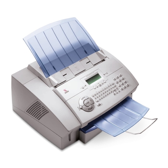
Page 97: Gp 5A Operation Elements (110V)
General Procedures / Information GP 5A Operation Elements (110V) Document Input Tray Document Output Tray Paper Output Tray Print Cartridge Serial Number Power Input Figure 1 FaxCentre F110 12/04 6-11... -
Page 98: Gp 5B Operation Elements (220V)
General Procedures / Information GP 5B Operation Elements (220V) Document Input Tray Document Output Tray Paper Output Tray Print Cartridge Serial Number Power Input Figure 1 6-12 12/04 FaxCentre F110... -
Page 99: Gp 6A Control Panel And Lcd Display (110V)
General Procedures / Information GP 6A Control Panel and LCD Display (110V) Figure 1 FaxCentre F110 12/04 6-13... -
Page 100: Gp 6B Control Panel And Lcd Display (220V)
General Procedures / Information GP 6B Control Panel and LCD Display (220V) Figure 1 6-14 12/04 FaxCentre F110... -
Page 101: Gp 7 Printable Lists
Received fax printing Authorization RECEPTION Setting number of fax Copies and sorting Table 3: Print FUNCTIONS LIST Function list printing LOGS Print TX and RX logs DIRECTORY Print the directories SETUP User parameters printing COMMANDS Printing of commands list FaxCentre F110 12/04 6-15... - Page 102 The current settings on your machine can be seen on your list of parameters. Press Menu, 44 and then the OK button to obtain this list. Example of the list: SID: Service Number: 1234567 Date: 16-08-05 16:34 Table 1: COUNTRY Oesterreich LANGUAGE English DATE / TIME 16-08-2005 16:34 6-16 12/04 FaxCentre F110...
- Page 103 Mode Pages Durat. Status Note 12-08 17:18 0’04” Code 03 User break 12-08 17:20 +43 1 60101 4875 Normal 1 0’34” Correct 12-08 17:40 0’06” Code 03 User break 19-08 13:54 0’06” Code 03 User break FaxCentre F110 12/04 6-17...
- Page 104 This list provides a list of the numbers stored in your machine. This list is accessed by pressing Menu, 43 and then the OK button. Example of the list: SID: Service Number: 1234567 Date: 16-08-05 16:34 Table 1: Name Number Directory 06641234567 06647654321 John Peterson 00431661554567 Sandra Douglas 06763006777 6-18 12/04 FaxCentre F110...
-
Page 105: Gp 8 Service Functions
GP 8 Service Functions The FaxCentre F110 is equipped with a set of logic blocks referred to as SOS (SOFT Switch) num- bered 1 to 30. Each block consists of 8 bits called bit 1 to 8. Each bit can take a value of either 0 or 1. - Page 106 Values 0: no 1: yes Table 6: SOFT-Switch 6: Line Tests SOS- Reserved Reserved Reserved Reserved Reserved Reserved Reserved TSTDCOM: Driver test functions Values 0: no 1: yes SOFT-Switch 7, 8: Reserved 6-20 12/04 FaxCentre F110...
- Page 107 SOFT-Switch 11,12: Reserved SOFT-Switch 13,14,15,16: Internet Functions (Not Used) Table 9: SOFT-Switch 17: Communication Reserved Reserved Reserved SOS-NO-TRT- Reserved Reserved Reserved Reserved FCERROR: retry after modem high data detect. Problem Values 0: yes 1: no FaxCentre F110 12/04 6-21...
- Page 108 0: no 0: garbage 0: for each line 1: yes collection with an error when 1: only once, application then destroy terminates 1: garbage collection as background task ATTENTION: taken into account only after reboot of 6-22 12/04 FaxCentre F110...
- Page 109 0: country dep. 1: yes 1: opposite 1: Text2Fax Table 16: SOFT-Switch 25: Miscellaneous Software Functions SOS- Reserved Reserved Reserved Reserved Reserved Reserved Reserved DBL_ALT: Photocoupler Type for ring detection Values 0: single alternance 1: double alternance FaxCentre F110 12/04 6-23...
- Page 110 10: 1,7 MHz 11: unused (1MHz) Table 20: SOFT-Switch 29: Miscellaneous Software Functions Reserved Reserved Reserved Reserved Reserve Reserved User User function function paper contrast format Values 0: disabled 0: disabled 1: enable 1: enable SOFT-Switch 30: Reserved 6-24 12/04 FaxCentre F110...
-
Page 111: Gp 9 Maintenance Functions
Clear document memory (received documents, documents to be sent) Clear Sending command list Clear Printing command list Directory is preserved Pages counters are preserved Consumables counters are preserved Communication log is preserved User parameters are preserved Menu # 9 Same as Menu # 7 FaxCentre F110 12/04 6-25... - Page 112 Menu * Y - If consumer counter value is higher than near end (6%), set counter value to 6%. Menu * y - If consumer counter value is lower than near end (6%), set counter value to 1% 6-26 12/04 FaxCentre F110...
-
Page 113: Gp 10 Test Function
Description of Test for Service Enter Test Mode First you have to set the FaxCentre F110 into maintenance mode. (SOS1-Bit8 has to be set to one) To enter in the Test Mode press the Key combination below on the keypad:... - Page 114 All test flows are described in the form outlined. The field Step is for orientation in case of Jumps, Status is for decisions, Operator describes the actions of the Operator, UUT describes the actions for the FaxCentre F110, Display shows the Text during a Test, and Remarks is for added Infor- mation.
- Page 115 General Procedures / Information Description of Test for Service INIT Testmode (Test-Code 100) This function is for initializing the TEST MODE if the FaxCentre F110 was in USERMODE. Input Code 100 and then the parameter 00. Flow Table 1: Step...
- Page 116 108 TESTMODE XX XX <> 00 or anomaly occurred Pass: The sounds are clear to hear and the operator pressed <START>. Resultbyte: 00 … Test done and OK FF …Test not done 80 … Operator pressed <STOP> 6-30 12/04 FaxCentre F110...
- Page 117 <a>, <s>, <d>, <f>, <g>, <h>, <j>, <k>, <l>, <.>, <Enter> SHIFT+<Z>, <x>, <c>, <v>, <b>, <n>, <m>, < >,CTRL+<@> <SMS>, <Redial>, <R>, <Dial> <1>, <2>, <3>, <4>, <5>, <6>, <7>, <8>, <9>, <*>, <0>, <#> <Res.>, <Copy>, <Clear>, <Stop>, <Start> FaxCentre F110 12/04 6-31...
- Page 118 0.3 s. From this the cycle gives up for the 6th icon: 0 x5F, 0 x2E, 0 x79, 0 x42. Sign (0 x48) are written to, X, on all readable characters. Controller check (0 x8A) are written to, o, on all readable characters. 6-32 12/04 FaxCentre F110...
- Page 119 Press <STOP> 110 TESTMODE XX XX <> 00 or anomaly occurred Pass: All Tests ok, no anomaly occurred. Resultbytes: Test ... ok FF ... Test not done All other bit combinations means error (anomaly occurred). FaxCentre F110 12/04 6-33...
- Page 120 Press <STOP> Set Resultbyte to XX 111 TESTMODE XX XX <> 00 or anomaly occurred Pass: All Tests ok, no anomaly occurred. Resultbytes: 00 ... Test ok FF ... Test not done 80 … Operator pressed <STOP> 6-34 12/04 FaxCentre F110...
- Page 121 XX = 00 and no anomaly occurred Set Resultbyte to XX 112 TESTMODE XX <> 00 or anomaly occurred Pass: Resultbytes: 00 ... Test ok FF ... Test not done All other bit combinations means error (anomaly occurred). FaxCentre F110 12/04 6-35...
- Page 122 120 TESTMODE 00 XX = 00 and no anomaly occurred Press <STOP> Set Resultbyte to XX 120 TESTMODE XX XX <> 00 or anomaly occurred Pass: All Tests ok, no anomaly occurred Resultbytes: Test ok Test not done 80 … Operator pressed <STOP> 6-36 12/04 FaxCentre F110...
- Page 123 General Procedures / Information EXIT Testmode (Test-Code 136) This function exit‘s the TEST MODE if the FaxCentre F110 is in TEST MODE. After exit the Fax- Centre F110 is in USERMODE. Flow: Step Status Operator Display Remarks Is in TESTMODE YYY TESTMODE YYY…last Testcode...
-
Page 124: Gp 11 Firmware Upgrading With Pc Kit V1.1 (Windows 2000 / Xp)
You can drag and drop a file from the Explorer to the TelUSB2 utility. • You can use the “Browse” button. • You can directly write the full path of the file in the edit filed. 6-38 12/04 FaxCentre F110... - Page 125 5. Confirm with OK and then press STOP to exit. 6. Press MENU * 4 to activate the TELELOADING function. Display show: TELELOADING IN PROGRESS 7. Start the program TelUSB2.exe for example with double click on the Teleloader icon. FaxCentre F110 12/04 6-39...
- Page 126 After a while the device will continue with a reboot and starts with the easy install procedure, 11. Go through the easy install procedure, 16, to finish the update process. 12. Make a “ White Reference (Menu * W) “ adjustment. 6-40 12/04 FaxCentre F110...
-
Page 127: Gp 12 Customisation Of The F110 Faxcentre Machine
Reading the customization of a Machine For reading the customization use the following command: commfl #10112 This command means reading Then the output should be like this: Sending #10112 … #10112 sent. Reading … Returned: 0000040*7007 FaxCentre F110 12/04 6-41... - Page 128 The upload is done with Commflag too. The command is very similar to reading: #1021200040*7007 commfl This Checksum The amount The byte of means for the of the digits write customizati of the customization mode. on byte. customizatio file converted n file. into ASCII code. 6-42 12/04 FaxCentre F110...
- Page 129 0*70 00040*7007 • Type: • "commflag upload xed" to set the machine to Xerox Europe Wave1 (UK, FR, DE, SP, NL, IT) • • "commflag upload xee" to set the machine to Xerox Europe Wave2 (East Europe, BE, PT)+ •...
- Page 130 -x The more advanced way is a combination with the upload and check command. Only attach a – x at the end of the command. These are two examples: commflag check –x commflag upload <shortcut> -x 6-44 12/04 FaxCentre F110...
-
Page 131: Gp 13 Hardware Architecture
This document is the specification for Mainboard FaxCentre F110. Functional Description General Purpose This document describes the hardware architecture for FaxCentre F110. The core is based on Digicolor2 ARM9 & video processor. Four equipment of the same PCB are planned: •... - Page 132 During the boot sequence, the compressed code stored into the Flash memory is copied and ex- panded into the SDRAM to be executed. Timers 4 timers 32 bits for general use are available into the Digicolor2. Timers are derived from the main clock digicolor2. 6-46 12/04 FaxCentre F110...
- Page 133 CLK_EXT: This pin is sampled during the assertion of chip reset. A pull-down resistor assert a "0" so internally generated clocks will be used. After exiting reset, this pin is con- figured to output. Clk_Ext pin can be driven with an internally generated clock waveform or static value. FaxCentre F110 12/04 6-47...
-
Page 134: Gp 14 Power Supply
To reach the lowest possible power consumption some parts are switched off or set to low-power mode. During power save mode, the following parts are switched off: • Paper motor driver • LSU and polygon motor • • Loudspeaker amplification • Paper sensors • ADC Z350 6-48 12/04 FaxCentre F110... -
Page 135: Gp 15 Installation Requirement
• Avoid locations where water or other products might be splashed on to the machine. • The machine should not be installed directly on to the floor. • Place the machine on a flat horizontal support. FaxCentre F110 12/04 6-49... -
Page 136: Gp 16 Easy Install
GP 16 Easy Install Easy Install is the process used when a machine is initially connected. A series of questions are asked to guide the user to set up the machine correctly. e.g. country, date and time etc. 6-50 12/04 FaxCentre F110... -
Page 137: Gp 17, 18 Not Used
General Procedures / Information GP 17, 18 Not Used FaxCentre F110 12/04 6-51... -
Page 138: Gp 19 Printer Interface
Motor driver DC bipolar L6219 Buffer stepper (STM) m otor Paper sensors PIC KUP* Solenoid High voltage Halogen lamp PCLK PST ART * PRDY * Video_Clk HSYNC* EPLD VDO2 Video LD_EN LDEN * -S/H Figure 1 6-52 12/04 FaxCentre F110... -
Page 139: Gp 20 Usb Device
Note: Input or Output direction from the Digicolor2 side. Note: An external transistor circuit drive the pull-up resistor (1.5KW) on the D+ signal for high speed USB device. The transistor protects Digicolor I/O from abnormal connection. FaxCentre F110 12/04 6-53... -
Page 140: Gp 21 Lsu
The nominal main clock is set at 92Mhz. The base clock used by the Pixel Output section is set to Mainclock / 4 = 23MHz. The parameter Ack_Assert in the register PO_COUNT_CONTROL is set to 1 which gives a video clock of 11,5MHz(Base Clock / 2). 6-54 12/04 FaxCentre F110... - Page 141 If the main clock is set to 92MHz, it gives 675.65us per line. The motor period is Tmotor=675.65/1.5= 450,43us which gives 2220.11Hz. The motor needs 6 clock cycle for a complete round. The clock is an output of the PWM regulator. FaxCentre F110 12/04 6-55...
-
Page 142: Gp 22 Operation Panel Unit Interface
OPU is controlled with digicolor2 serial link USART0 and I/O. LCD access is write only. Other signal for LCD control are sent through serial link TX (4 parallel data bit & RS (Register Select)). The sensors are only supplied if PSAVE_OPU is low. 6-56 12/04 FaxCentre F110... -
Page 143: Gp 23 Motor Control
RC filters R260, C253 and R261, C254. The current in each phase is sensed by two 1ohm resistor in parallel: R266, R267. In this application, the maximum current is set to 600mA. FaxCentre F110 12/04 6-57... -
Page 144: Gp 24 Sensor / Actuator
Pick up 2nd page Pick up first page Page detected page begins to get page out of the out of the machine page begins to get machine out of the machine page out of the cassette Figure 1 6-58 12/04 FaxCentre F110... -
Page 145: Gp 25 Heat Control
The output of the thermistor is measure through an ADC to enable an accurate regulation of the temperature. See following diagram for the normal behaviour. 165°C±3°C 145°C±3°C Ambiant: 25 °C Fuser command Fan command Full speed Half speed Waiting for Inactivity: Waiting Cooling Preheating: 15s Printing information time: 4-5min down Figure 2 FaxCentre F110 12/04 6-59... -
Page 146: Gp 26 Power Supply Interface
Toner management PRBEN*: Enables the high voltage output to charge the drum. DBEN*: enables the high voltage output to precharge the toner. To protect the output of the Digicolor, these two outputs should be properly buffered. 6-60 12/04 FaxCentre F110... -
Page 147: Gp 27 Adc For Temperature And High Voltage Control
The signal CS_ADC is used to properly multiplex the smart card interface with the ADC interface. When the ADC interface is active, the signal CS_ADC is set to 0. When the smart card interface is active, the signal is set to 1. FaxCentre F110 12/04 6-61... - Page 148 HSYNC. After the first line, the counter is automatically reloaded and restarted at each end of line. Smartcard and ADC mutiplexing The EPLD filters all signals coming from the Digicolor during ADC operations and disable the ADC during smartcard operations. 6-62 12/04 FaxCentre F110...
-
Page 149: Gp 28 Fuser Interface
The fuser interface is protected against excessive temperature. • HEATER = FUSER nor THERM_IN FUSER is set to 1 by the firmware to switch on the heater. When the temperature raises above the maximum limit, THERM_IN is set to 0 by the hardware. FaxCentre F110 12/04 6-63... -
Page 150: Gp 29 Scanner Interface
The CIS is controlled using 2 signals: • CLK: Pixel clock. The maximum frequency is 2MHz. • SI: Start pulse to begin a new scanning line. This signal is active high and should last one clock cycle. 6-64 12/04 FaxCentre F110... -
Page 151: Gp 30 Led Management
Set to 92mA for 200DPI CIS. The source is switched on/off by the signal LED_G. The minimum forward voltage is 17.4V, the maximum 18.9V, so the source current should withstand a Vce be- tween xxxV and xxxV, and a maximum power of 1W. FaxCentre F110 12/04 6-65... -
Page 152: Gp 31 Afe
Q320. This amplifier can be short cut by the resistor R312. The Digicolor controls the ADC through a serial link and gets the data through a pixel bus (PI_DATA7..0). The reference voltages are filtered by 100nF in parallel with a 22uF to minimise the ripple. 6-66 12/04 FaxCentre F110... -
Page 153: Gp 32 Motor Control
After reset the motor buffer must be forced to the value 00h.The signal AE1* is controlled as output "0" to access motor and "1" for motor stand-by. The driver is protected against overvoltage by a xxxV zener diode connected to the COM pin. FaxCentre F110 12/04 6-67... -
Page 154: Gp 33 Sensor
ADF is empty. DPS: Document position sensor. This signal is 1 when there is no paper in the feeder and 0 oth- erwise. This sensor is used to detect a change of page while scanning a document. 6-68 12/04 FaxCentre F110... -
Page 155: Gp 34 Modem & Line Interface
The protection block protects the circuit against surges on the lines up to +8kV in common mode and provides some filtering for EMC. This block should not have any effect on sinusoid signal up to 120Vrms with an offset of 60Vdc. FaxCentre F110 12/04 6-69... - Page 156 The ring signal is specified by its amplitude, its frequency and the cadence (On- and Off-time re- lationship). The ring signal transmission is terminated when a valid loop current is detected by the network. The ring amplitude is added to the line On-Hook voltage. 6-70 12/04 FaxCentre F110...
- Page 157 Ring signal status (RING) changes if PD changes, a line break occurred or an external or parallel phone has taken the line ! Table 1: RING State Default, no line transition occurred Ring or Polarity Reversal FaxCentre F110 12/04 6-71...
- Page 158 External loop current status (EXT_LOOP) also changes if PD changes Ringer applied Parallel Phone state changes Line polarity reversal Flash key dialled The two signals EXT_LOOP and INT_LOOP are then used by the firmware to decide whether or not switch the relay. 6-72 12/04 FaxCentre F110...
- Page 159 Current Modulation. The signal is used during Pulse Dial only to enhance the switching charac- teristics of PD (Loop Current). Keep activated during dialling of a complete digit. Not activated if flash is dialed. Table 7: CURMOD State Default, no current Loop current enforced FaxCentre F110 12/04 6-73...
- Page 160 Z852 amplifies the signal. The high impedance path is muted during off-hook by the tran- sistor Qxxx. To switch on/off this path, the voltage is measured in parallel with the DC character- istics. The threshold level is given by R878 and R876. 6-74 12/04 FaxCentre F110...
- Page 161 (HOOK=0), establishes a connection between the network and the parallel terminal equipment only. Due to the source resistance change of the parallel terminal equipment the voltage drops from an idle state (On-Hook) to a connection state (Off-Hook). FaxCentre F110 12/04 6-75...
- Page 162 The digits that are used to specify a phone number are coded by the number of line disconnection’s and reconnections. These voltage and current chang- es a mirrored at the line signals 6-76 12/04 FaxCentre F110...
- Page 163 LA, LB changes. On-Hook Polarity Reversal On-Hook LA, LB [+V] + max. On-Hook On-Hook Signalling + min. Off-Hook - min. Off-Hook On -> Off-Hook transition time [-V] Figure 11 FaxCentre F110 12/04 6-77...
-
Page 164: Gp 35 Intloop Signal
NO EXT. PHONE Offhook / Handset lifted 1 LOOP DET. INTERNAL Offhook / Pulse Dial LOOP DET. INTERNAL Offhook / DTMF Dial LOOP DET. INTERNAL Offhook / FAX LOOP DET. INTERNAL Offhook / No Loop NO LOOP INTERNAL 6-78 12/04 FaxCentre F110... - Page 165 Figure 2 Parallel Terminal Equipment Off-Hook(FCU Off-Hook) When a parallel terminal equipment, connected directly to the line, goes Off-Hook, it reduces the line voltage, which results in a drop of the loop current that may be detected. FaxCentre F110 12/04 6-79...
- Page 166 The line voltage changes the polarity as well as the idle loop current, but has no effect if LIU_HOOK=0 and may have an effect if LIU_HOOK=1. Pulse-Dial The signalling during Pulse-Dial has been described in detail with PD Pulse-Dial. The current changes during Pulse-Dial are mirrored by INTLOOP. 6-80 12/04 FaxCentre F110...
-
Page 167: Gp 36 Extloop Signal
Loop Current External On-Hook External Off-Hook [mA] min. Loop Current threshold No External Loop Idle Loop Current External Loop Current settling Valid External Loop Current EXTLOOP Figure 2 FaxCentre F110 12/04 6-81... - Page 168 Off-Hook, a loop current is drawn and the loop detection signal is activated (EXTLOOP = 0). The external loop current is equivalent to the loop current. Due to other LIU ac- tivities (Incoming Ring, Pulse Dial etc.) the loop detection signal (EXTLOOP) may change errone- ously ! 6-82 12/04 FaxCentre F110...
- Page 169 Parallel Terminal Equipment Off-Hook(On-Hook) The line voltage change due to parallel Off-Hook has some effect on the internal loop detection (EXTLOOP). If the parallel phone is Off-Hook in addition the loop current signal may be lost (change) erroneously ! FaxCentre F110 12/04 6-83...
-
Page 170: Gp 37 Ring
Due to the possibility of connecting a parallel terminal equipment which, when also internal Off- Hook, reduces the line voltage which may result only in a reduction of the loop current. This line voltage change may also introduce an invalid ring detection pulse ! 6-84 12/04 FaxCentre F110... - Page 171 ! If a parallel phone has seized the line changing of the line voltage, due to the dialled digits, may also generate an invalid polarity reversal detection pulse ! FaxCentre F110 12/04 6-85...
- Page 172 Due to the possibility of connecting a parallel terminal equipment which, when also internal Off- Hook, reduces the line voltage which may result also in a reduction of the loop current. This line voltage change may also introduce an polarity reversal detection pulse ! 6-86 12/04 FaxCentre F110...
-
Page 173: Gp 38 Liu_Hook
To draw a valid loop current the dial control signal (Hook/Pulse Dial control signal, PD) has to be activated (PD = 0)in addition. Ext Loop Line PSTN Network Line LIU_HOOK IntLoop Terminal Equipment Internal phone On Hook Figure 1 FaxCentre F110 12/04 6-87... - Page 174 To signal a valid preparation for CLI reception, a short loop current pulse is drawn from the net- work. This is handled by activating the line connection switch (HOOK) for a defined duration. Valid Loop Current Line Current Idle Loop Current HOOK Wetting Pulse time Figure 2 6-88 12/04 FaxCentre F110...
-
Page 175: Gp 39 Pulse Dial
The digit of a phone number corresponds to the number of disconnection’s (Break) and reconnec- tions (Make). A digit ‘3’ has three ‘Breaks’ and three ‘Makes’. The PD pulse duration relationship of break-time and make-time is country specific. FaxCentre F110 12/04 6-89... - Page 176 Figure 3 CLI Services To signal a CLI service transmission start, during CLI service handling, the terminal equipment has to draw a current pulse from the network (Wetting Pulse) by activating PD. (see HOOK Signal Description) 6-90 12/04 FaxCentre F110...
-
Page 177: Gp 40 Curmod
CURMOD Set-up (General) In general the CURMOD is activated with the first make and handled like the Pulse dial port in- cluding the last break, where the CURMOD port is deactivated. break make CURMOD DMO_on Figure 2 FaxCentre F110 12/04 6-91... - Page 178 The CURMOD port is activated before the first break and kept active until the last make of the digit is done. If several digits are dialled, the CURMOD stays active until the last make of the last digit is done. 6-92 12/04 FaxCentre F110...
-
Page 179: Gp 41 Cidimp
If activated a impedance is connected in parallel to the nominal source impedance of the terminal equipment. Table 1: CLI Impedance Table LIU state HOOK CIDIMP LOOP Description Onhook / No CLI No CLI Impedance handling Onhook / CLI CLI Impedance Impedance Onhook / CLI Draw loop current Wetting Pulse FaxCentre F110 12/04 6-93... -
Page 180: Gp 42 Mute
(MTXD), the mute signal disables the voice path if activated. The MUTE signal has to be activated prior dialling of a number and has to be deactivated, to re-establish the voice path, after the digit has been dialled. 6-94 12/04 FaxCentre F110... -
Page 181: Gp 43 Off_Hook
To indicate the lifting of the handset to seize the line or to record voice during TAM handling a change of this signal has to be detected. No line access is established by activation of the cradle signal only. A corresponding LIU configuration has to be executed to establish a valid line connec- tion. FaxCentre F110 12/04 6-95... - Page 182 The chip modem is an Agere data pump (DP2Vxx) + CODEC (1034C). V32 to V90 data pump can be used. The data pump is supervised by digicolor2 on peripheral bus. The line interface can manage an external telephone. 6-96 12/04 FaxCentre F110...
- Page 183 The output of the multiplexer is amplified by two LM358 (Z551 section 1 and 2) and the by a dis- crete amplifier (Q550 and Q551). Table 2: State VOL3 VOL2 VOL1 VOL_EN* OUTP Ringer high Ringer medium Ringer low Line monitoring high Line monitoring medium Line monitoring low Mute FaxCentre F110 12/04 6-97...
- Page 184 216 x 356mm Paper Thickness 0.08 – 0.12mm Paper Weight 60 – 90gms (16lb-24lb) Legal: 90gsm Paper Tray Max. 250Sheets Table 3: Print Cartridge Capacity (5% Black) Starter Cartridge Approx. 1000 Pages Additional Cartridges Approx. 3000 Pages 6-98 12/04 FaxCentre F110...
- Page 185 Table 8: Scanner Type Black and White, 256 grey tones Resolution 300 x 300dpi Scan Area Max. 218 x 600mm (8.5 x 24 inch) Scan Width 208mm Speed 6sec. / A4-Page (Letter 8.5 x 11 inch) FaxCentre F110 12/04 6-99...
- Page 186 Table 9: Telephone Type Public Switched (PSTN) Private Branch Exchange (PABX) Telephone Book Entries Approx. 200 Table 10: SMS (Short Message Service) * Gateway Memory 30 Messages Message Length 640 Character * Depending on country and telephone network 6-100 12/04 FaxCentre F110...
- Page 187 • test results recorded • serial numbers recorded Terminals / plugs UUT >>> TNV = PSTN-line – ext. SELV = USB = Body = chassis AC POWER = power terminal – plugs FaxCentre F110 12/04 6-101...
- Page 188 4) High voltage – Test -> 100 % - Test PSTN ( TNV-3 ) / AC power with a voltage of 4240 V DC is performed between TNV-3 and power source in conformity to IEC/EN 60950-1:2001, clause 5.2.2 (table 3b): U = 4240 V DC; I max = 0,25 mA ; t min > 1 s 6-102 12/04 FaxCentre F110...
- Page 189 PSU ... Power Supply Unit • OPU ... Operation Panel Unit (Control Panel) • LIU ... Line Interface Unit for Fax • MAB ... Main Board • ADC ... Analogue to Digital Converter • AFE ... Analogue Front End FaxCentre F110 12/04 6-103...
- Page 190 General Procedures / Information Page intentionally blank 6-104 12/04 FaxCentre F110...
- Page 191 7. Wiring Data WD 1 Connector to PSU (P350) ....................WD 2 Connector to CIS (P300) ....................WD 3 External Connection ....................... WD 4 Connector to LSU (P351) ....................WD 5 Connector P402 ......................WD 6 Wiring Diagram ....................... FaxCentre F110 12/04...
- Page 192 Wiring Diagrams Page intentionally blank 12/04 FaxCentre F110...
-
Page 193: Wd 1 Connector To Psu (P350)
Refer to GP 26 WD 6. Table 1: Signal Signal +24V after switch +24V after switch PRBEN* TRREAD TRPWM RTRBEN* DEBEN* PAPER* REGIST* PICKUP* +24V +24V -12V HEAT FAN* PMOTB0* PMOTA0 PMOTA0* PMOTB0 SMOTB0* SMOTB0 SMOTA0* EXIT* SMOTA0 FaxCentre F110 12/04... -
Page 194: Wd 2 Connector To Cis (P300)
Wiring Diagrams WD 2 Connector to CIS (P300) Refer to GP 29 WD 6 Table 1: Signal VDD(+5V) GLED VLED 12/04 FaxCentre F110... -
Page 195: Wd 3 External Connection
Table 4: DECT connector(P900) Signal Digicolor2 Comment Power supply 5V USART1_T Serial data receive USART1_R Serial data transmit DECT_RES Reset for the dect base AGND Analog ground (earth) Audio_in Audio in Audio-out Audio out Agnd Analog ground (earth) FaxCentre F110 12/04... -
Page 196: Wd 4 Connector To Lsu (P351)
Motor rotation detection (Low=synchronised) *START Motor rotation (Low=Start ; High=Stop) Ground (Earth) +24V Power supply Not connected Ground (Earth) Video* Video signal LDEN* LED enable -S/H* Enable LED power control Power supply Ground (Earth) Ground (Earth) *HSYNC Horizontal synchronisation 12/04 FaxCentre F110... - Page 197 Ground (Earth) CS_LCD* PP_nACK LCD chip select CS_PAN* PP_nSTROBE Keypad chip select TX_PAN USART0_TX Serial link TX RX_PAN USART0_RX Serial link RX Ground (Earth) SCLK_PAN USART0_CK Serial link clock GP_A2 Document sensor (ADF) PI_TGEN0 Document position sensor(ADF) P3.3VOPU FaxCentre F110 12/04...
-
Page 198: Wd 6 Wiring Diagram
Wiring Diagrams WD 6 Wiring Diagram Figure 1 12/04 FaxCentre F110... - Page 200 Page intentionally blank...
- Page 201 XEROX EUROPE PUBLICATION COMMENT SHEET Please copy this master sheet and use it to help us to improve this publication. We would like you to tell us about improvements to its accuracy, format and quality. Please give specific references, i.e.: page numbers and figure numbers and attach marked up photocopies wher- ever possible.
- Page 202 XEROX EUROPE...
- Page 203 Page 1 of 2 APPENDIX A: Health & Safety Incident Report Involving a Xerox Product Customer Identification Customer Name: Name of Customer Contact Person: Address: E-mail: Telephone : Fax : Customer Service Engineer Identification Name: Employee : Pager : Location:...
- Page 204 E-Mail: Mailing Address: Date Report Submitted: Instructions: E-mail or fax this completed form to EH&S: ž For incidents in Xerox Europe and Developing Markets East (Middle East, Africa, India, China, and Hong Kong) please e-mail: Elaine.Grange@gbr.xerox.com or fax: +44 (0) 1707 35 3914 [intelnet 8*668 3914] Note: - If you fax this form, please also send original by internal mail ž...