Table of Contents
Advertisement
Available languages
Available languages
Quick Links
Advertisement
Table of Contents

Related Manuals for Midland ALAN 54 E


Summary of Contents for Midland ALAN 54 E
- Page 1 ® BEDIENUNGSANLEITUNG ALAN 54 E...
-
Page 2: Funktion Und Lage Der Bedien-Und Anzeigenelemente
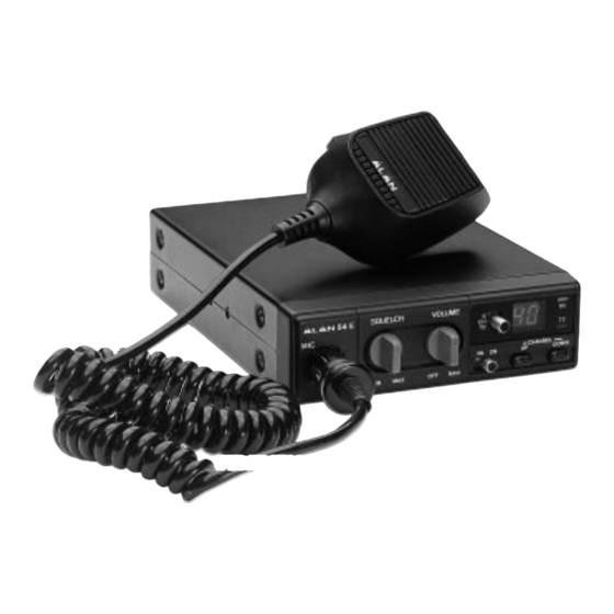
19: Schnellschaltung auf Kanal 19 Mikrofonhalterung Bedienungsanleitung Geräterückseite Anmelde- und gebührenfrei Ihr ALAN 54 E ist europaweit als CB-Funkgerät zugelassen. Als reines FM-Gerät ist es in Deutschland anmelde- und gebührenfrei. Funktion und Lage der Bedien- und Anzeigenelemente 54 E SQUELCH... -
Page 3: Mikrofon
Armaturenbrett Maschinenschrauben (M4x10) Der Antennen-Anschluß ANT Ihres ALAN 54 E weist eine Impedanz von 50 Ohm auf. Sie müssen eine CB-Mobilantenne oder Blechschrauben 4x10 mm mit derselben Impedanz verwenden und diese über ein Koaxialkabel (ebenfalls mit 50 Ohm Impedanz) mit der Rändelschraube... -
Page 4: Niemals Ohne Antenne Senden
Schnellschaltung für Kanal 9 und 19 Niemals ohne Antenne senden! Ihr ALAN 54 E verfügt über eine Schnellschaltung, mit der Sie sofort die Anrufkanäle 9 oder 19 aufrufen können. Senden Sie niemals ohne angeschlossene Antenne. Senden Sie auch dann nicht, wenn das Verbindungskabel Diese Umschaltung wird mit Schiebeschalter „9 CH 19“... -
Page 5: Externer Lautsprecher
Der Zusatzlautsprecher muß eine Impedanz von 4-8.Ohm und eine Belastbarkeit von min. 3 Watt aufweisen. Der Frequenzkanaltabelle Anschluß erfolgt über einen 3,5 mm Klinkenstecker. Externer Lautsprecher Im ALAN 54 E ist bereits ein Lautsprecher eingebaut. Sie können aber auch einen externen Lautsprecher einsetzen Kanal-Nummer Frequenz (MHz) Kanal-Nummer Frequenz (MHz) und diesen an einer akustisch günstigen Stelle im Auto montieren. -
Page 6: Table Of Contents
Praxistips für den Funksprechverkehr INHALT Um einen reibungslosen Funkverkehr zu gewährleisten, sollte sich jeder Funkteilnehmer an folgende Grundregeln Funktion und Lage der Bedien-und Anzeigenelemente ............1 halten. Geräterückseite ........................2 1. Nach einem Kanalwechsel sollte immer erst einen Moment mit geöffneter Rauschsperre kontrolliert werden, ob Mikrofon ........................... - Page 7 ALAN 54 E Your 40 channel Mobile CB represents the state-of-the art in high-tech engineering. Designed for 40 FM channel Citizen Band Mobile operation, this compact package is big in performance. It is a quality piece of electronic equipment, skillfully constructed from the finest components. The circuitry is all a solid - state, mounted on rugged printed circuit boards.
- Page 8 The most common mounting position for a transceiver is under the dashboard directly over the drive shaft hump. Do not The above discussion is as important for reception as it is for the transmission. If a mismatch exists between the antenna mount the transceiver in the path of the heater or air conditioning air stream.
- Page 9 CONNECTING THE LOCKING MICROPHONE PLUG REMOTE SPEAKER OPERATION Your transceiver features a new locking microphone connector. This ensures that you won’t accidentally pull out or An 4 Ohm, speaker, rated at 3-10 watts, should be used for this function. Plug the speaker into the EXT SPKR jack at loosen the plug connection when moving the microphone cable out.
- Page 10 TECHNICAL SPECIFICATIONS FREQUENCY RANGES: Frequency range ......................... 26.965-27.405 MHz Channel No. Frequency (MHz) Channel No Frequency (MHz) Channels ................................40 FM Mode of operation ..............................PLL 26.965 27.215 Ω Antenna impedance ............................50 26.975 27.225 Power supply ............................. nom. 13,8V DC Microphone ............................
- Page 11 Some Hints to heop you enjoy your C.B. CONTENTS 1. Wait for a pause in transmission before asking for a break. 2. If you don’t reeceive any answer after a second call to another station, sign off and allow othe to use the channel Function and location of the controls ..................
- Page 12 PRINTED CIRCUIT BLOCK DIAGRAM...
- Page 13 ELECTRICAL DIAGRAM...