Advertisement
Advertisement

Related Manuals for Midland ALAN 48 PLUS MULTI B


Summary of Contents for Midland ALAN 48 PLUS MULTI B
- Page 1 Alan 48Plus Multi B ” I N S T R U C T I O N GU I D E...
-
Page 2: Table Of Contents
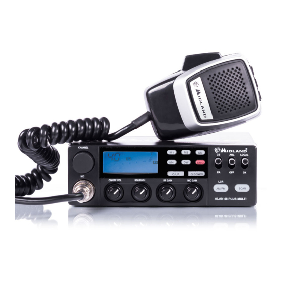
INDEX Your ALAN 48 PLUS MULTI B represents the state-of-the art in high-tech engineering. Designed for the Citizen Band Mobile operation, this compact package is big in performance. It is a quality piece of electronic equipment, Introduction ........................Pag. 1 skillfully constructed with the finest components. -
Page 3: Function And Location Of The Controls
FUNCTION AND LOCATION OF THE CONTROLS Channel selected number The received signal strength and the power of the transmitting signal AM/FM mode RX/TX: TX=transmit mode; RX=receive mode SCAN mode EMG mode M1-M2-M3-M4: preset memory channels DW: Dual Watch activated Frequency band selected. LOW: displayed when the radio transmits in low power (this mode is possible with some frequency bands only –... -
Page 4: Rear Panel
REAR PANEL 10/11. “Q. UP-Q. DOWN” buttons: To skip 10 channels up (Q. UP) or 10 chan- nels down (Q. DOWN). 12. ’’CB/PA’’ Selector. In the “CB” position, the unit operates as a transceiver. You can use the PA (public address) function only if you connect a spea- ker to the PA jack. -
Page 5: Installation
MICROPHONE INSTALLING AN ANTENNA 1. Place the antenna as high as possible. 1. PTT: transmission button 2. UP/DOWN buttons: manual chan- 2. The longer is the antenna, the better will be the performance. 3. If possible, mount the antenna in the center of whatever surface you nel selector choose. -
Page 6: How To Operate With Your Transceiver
HOW TO OPERATE WITH YOUR TRANSCEIVER FREQUENCY BAND CHART Digits displayed Country Italy 40 CH AM/FM 4Watt 1. Screw the microphone plug into the microphone jack. 2. Make sure your antenna is securely connected to the antenna connector. Italy 34 CH AM/FM 4Watt 3. -
Page 7: Technical Specifications
TECHNICAL SPECIFICATIONS A readily accessible disconnect device shall be incorporated in the installation wiring. The disconnect device shall disconnect both poles simultaneously. GENERAL Hereby, CTE International declares that this device is in compliance with the essential requirements and other relevant provisions of Directive 99/05/EC. Channels ..............