
Related Manuals for Pfaff 8304-040


Summary of Contents for Pfaff 8304-040
- Page 1 -040 8304 -042 Instruction Manual This instruction manual applies to machines from the following serial numbers onwards: # 15055 296-12-18 419/002 Betriebsanleitung engl. 08.2002...
- Page 2 The reprinting, copying or translation of PFAFF instruction manuals, whether in whole or in part, is only permitted with our previous consent and with written reference to the source. PFAFF Industrie Maschinen AG Postfach 3020 D-67653 Kaiserslautern Königstr. 154 D-67655 Kaiserslautern...
-
Page 3: Table Of Contents
Contents Contents ................. Chapter - Page Safety ........................... 1 - 1 Regulations ........................1 - 1 General notes on safety ....................1 - 1 Safety symbols ......................1 - 2 Important points for the user ..................1 - 2 Operating and technical personnel ................1 - 3 .05.01 Operating personnel ...................... -
Page 4: Contents
Contents Contents ................. Chapter - Page Installation and commissioning ................. 8 - 1 Installation ........................8 - 1 .01.01 Adjusting the table height ..................... 8 - 1 .01.02 Connecting the compressed air ..................8 - 2 .01.03 Fitting the tape reel bracket ..................8 - 2 Commissioning ...................... - Page 5 Contents Contents ................. Chapter - Page Adjustment ........................ 12 - 1 Notes on adjustment....................12 - 1 Tools, gauges and other equipment ................12 - 1 Hot-air nozzle ......................12 - 2 Distance of hot-air nozzle from the feed rollers ............12 - 3 Changing the heating cartridge ...................
-
Page 6: Safety
Safety Safety Regulations This machine was built in accordance with the European regulations listed in the conformity and manufacturer’s declarations. In addition to this instruction manual, also observe all generally accepted statutory and other regulations and legal requirements - including those of the country in which the machine will be operated and all valid environmental-protection regulations. -
Page 7: Safety Symbols
Safety Safety symbols Danger! Special points to observe. Danger of hands being crushed! Danger of burns from hot surface! Danger from electric voltage! Caution Do not operate without finger guard and safety devices. Turn off the main switch and let the machine cool down before any setting up, maintenance or cleaning work! 1.04... -
Page 8: Operating And Technical Personnel
Safety Operating and technical personnel Operating personnel .05.01 Operating personnel are persons responsible for setting up, operating and cleaning the machine as well as for eliminating any faults which may occur. Operating personnel must observe the following: ● Always comply with the notes on safety in the instruction manual! ●... -
Page 9: Danger Warning
Safety Danger warning Fig. 1 - 01 Do not operate the machine without the protective cover 1 ! Danger of burns if the hot air nozzle 2 is touched! Do not put your fingers between protective cover 1 and swivel unit 3! Danger of crushing when swivel unit 3 is swung in and out of place! 1 - 4... -
Page 10: Proper Use
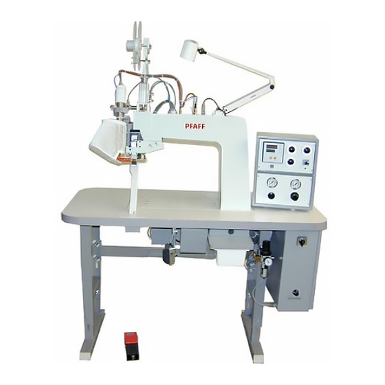
Proper use Proper use The PFAFF 8304-040 is a hot-air sealing machine with front off-set post. The PFAFF 8304-042 is a hot-air sealing machine with rear off-set post. The purpose of the machines is to heat-seal seams on waterproof and breathable membrane sheeting for leisure and hiking shoes and for all kinds of sportswear and weatherproof clothing, using a heat-sealing tape. -
Page 11: Specifications
Specifications ▲ Specifications Dimensions and weight: Length: ....................approx. 1265 mm Breadth: ....................approx. 600 mm Height: (without tape reel bracket) ............approx. 1450 mm Weight: ......................approx. 110 kg Mains voltage set for: ..............230 V± 10%, 50/60 Hz, single-phase Power input: .................... -
Page 12: Disposal Of The Machine
Disposal of the machine Disposal of the machine ● The proper disposal of the machine is the responsibility of the customer. ● The materials used on the machine are steel, aluminium, brass and various plastics. The electrical equipment consists of plastics and copper. ●... -
Page 13: Transport, Packing And Storage
Transport, packing and storage Transport, packing and storage Transport to the customer’s premises Within Germany the machine is delivered without packing. Machines for export are packed. Transport within the customer’s premises The manufacturer bears no liability for transport within the customer’s premises. Disposal of packing The packing of this machine consists of paper, cardboard, fusible fabric and wood. -
Page 14: Explanation Of The Symbols
Explanation of the symbols Explanation of the symbols In this Instruction Manual, tasks to be carried out and important information are drawn to your attention by symbols. The symbols have the following meanings: Note, information Cleaning, care Lubrication Servicing, repairing, adjustment, maintenance (only to be carried out by specialist personnel) 6 - 1... -
Page 15: Controls
Controls Controls Main switch ● The machine is switched on or off by turning main switch 1. Position " 0 " : Machine is switched off Position " I " : Machine is switched on When switching off the machine, please observe the notes in Chapter 8.03 Switching the machine on and off! -
Page 16: Knee Switch (Only On Machines With Tape-Cutting Device)
Controls Knee switch (only on machines with tape-cutting device) ● The heat-sealing tape is cut by operating knee switch 1. If required, the function can also be triggered by a second pedal, instead of by knee switch 1. Fig. 7 - 03 Temperature regulator / fault indicator ●... -
Page 17: Status Display Of Temperature Control
Controls Status display of temperature control ● Depending on the status of the temperature control, diodes 1 - 6 light up. Diode 1 lights up when the actual temperature deviates from the required temperature by +/-50°C. Diode 2 lights up, if the temperature exceeds 650°C, or if the sensor breaks. -
Page 18: Tape Feed Regulator/Hot-Sealing Speed
Controls Tape feed regulator/hot-sealing speed ● The feed of the sealing band is set with regulator 1. ● The hot-sealing speed is set with regulator 2. Fig. 7 - 07 Selection switch for operational modes ● The operational modes of the machine can be set with the selection switch 1 by means of four switch settings. -
Page 19: Regulator For Hot-Air Pressure
Controls Regulator for hot-air pressure ● The hot-air pressure is adjusted by turning regulator 1. ● The hot-air pressure level can be read from pressure gauge 2. The hot-air pressure must not drop below 0.2 bar! If the hot-air pressure is too low, there is a risk of the heating rod burning out. -
Page 20: Penetration Depth Adjustment Ring
Controls Penetration depth adjustment ring Switch off the machine! Danger of crushing between the housing and adjustment ring 1. ● The penetration depth (feed roller clearance) is set by turning adjustment ring 1. ● Before turning adjustment ring 1, the three screws 2 must be loosened (see also Chap. -
Page 21: Installation And Commissioning
Installation and commissioning Installation and commissioning The machine must only be installed and commissioned by qualified personnel! All relevant safety regulations must be observed!. Installation Suitable connections for power and compressed air, an even and firm floor surface and sufficient lighting must be provided for at the installation site. Adjusting the table height .01.01 Fig. -
Page 22: Connecting The Compressed Air
Installation and commissioning Connecting the compressed air .01.02 ● Connect the compressed air hose to coupling 1. ● Pull regulator 2 up and turn it until gauge 3 shows an air pressure of 6 bar. The air must be completely oil- free and dry. -
Page 23: Commissioning
Installation and commissioning Commissioning The machine must only be commissioned by qualified personnel. All relevant safety regulations must be observed. ! Check the machine, especially its electrical leads, for any damage. ! Have qualified personnel check that the machine can be operated with the local mains voltage and that it is correctly connected. -
Page 24: Setting Up
Setting up Setting up All setting-up work must only be carried out by appropriately trained personnel!.For all setting-up work , the machine must be disconnected by pulling out the mains switch. Inserting the sealing tape Adjusting the tape reel bracket to the diameter of the tape reel core .01.01 Fig. -
Page 25: Inserting The Heat-Sealing Tape / Adjusting The Tape Width And The Tape Brake
Setting up Inserting the heat-sealing tape / Adjusting the tape width and the tape brake .01.02 Requirement 1. The sealing tape should run easily through the narrow guide section. 2. The tape should run easily from the reel, but not be slack. Fig. -
Page 26: Adjusting The Penetration Depth
Setting up Adjusting the penetration depth The feed roller clearance depends on the thickness of the material to be sealed. The clearance is adjusted correctly, when one ply of the workpiece fits just between the feed rollers with the top feed roller lowered. Switch off the machine! Danger of crushing between the housing and adjustment... -
Page 27: Hot-Air Pressure, Hot-Sealing Temperature, -Pressure And -Speed
Setting up Hot-air pressure, hot-sealing temperature, -pressure and -speed Fig. 9 - 07 Fig. 9 - 06 ● Switch the machine on. Hot-air pressure: ● Adjust hot-air pressure on regulator 1 depending on the workpiece (at least 0.3 bar). ● To adjust the hot-air pressure on regulator 1 first set the pressure at “0”. Then adjust regulator 1 to the required level. -
Page 28: Heat Sealing
Heat sealing Heat sealing The machine must only be operated by appropriately trained personnel! The operating staff must also make sure that only authorized persons are in the danger area of the machine! Heat-sealing principle In order to achieve optimum heat-sealing, certain conditions concerning the workpiece and the machine settings have to be fulfilled. -
Page 29: Heat-Sealing Process
Heat sealing Heat-sealing process ● Select the correct machine setting for each material (see Chapter 9 Setting up) ● Place the workpiece between the feed rollers. ● Fix the material using the foot switch (first position). ● Using the foot switch (second position), move the hot-air nozzle into position – the feed rollers start automatically. -
Page 30: Care And Maintenance
Care and maintenance Care and maintenance Clean hot-air nozzle ................. daily, before use Check air pressure .................. daily, before use Clean water bowl of air filter/regulator ............ daily, before use Clean water bowl of fine filter ..............daily, before use Change fine filter ..................... -
Page 31: Check The Air Pressure
Care and maintenance Check the air pressure ● Before each use check the air pressure on gauge 1. ● Gauge 1 must show a pressure of 6 bar. ● Adjust this setting if necessary. ● To do so, pull knob 2 up and turn it until the gauge shows a pressure of 6 bar. -
Page 32: Draining The Water Bowl Of The Fine Filter/Changing The Fine Filter
Care and maintenance Draining the water bowl of the fine filter/changing the fine filter Switch off the machine! Remove the compressed air tube from the air filter/regulator. Draining the water bowl: ● Open drain plug 1 and drain water into water bowl 2. -
Page 33: Lubricating The Drive Chains
The intervals for lubrication depend on working conditions (dampness, soiling etc.). Only use sodium bicarbonate grease with a dripping point of 150°C and a fulling penetration of 375 – 405 mm /10 at 25°C. We recommend PFAFF chain lubricant, order no. 280-1-120 243. 11 - 4... -
Page 34: Adjustment
Adjustment Adjustment Notes on adjustment All adjustments in this manual are based on a fully assembled machine and may only be carried out by expert staff trained for this purpose. Machine covers, which have to be removed and replaced to carry out checks and adjustments, are not mentioned in the text. -
Page 35: Hot-Air Nozzle
Adjustment Hot-air nozzle Requirement 1. When hot-air nozzle 5 has been swung into place, it should be positioned in the centre of the feed roller 6 in feed direction. 2. The height adjustment of the hot-air nozzle 5 depends on the material and can be set from 5 –... -
Page 36: Distance Of Hot-Air Nozzle From The Feed Rollers
Adjustment Distance of hot-air nozzle from the feed rollers Requirement There must be distance of 1-2 mm between hot-air nozzle 3 and top feed roller 4. Fig. 12 - 02 ● Turn adjustment screw 1 (screw 2) according to requirement 1. 12 - 3... -
Page 37: Changing The Heating Cartridge
Adjustment Changing the heating cartridge Fig. 12 - 03 Wait until the heating element has cooled down! Danger of burns! Disconnect the mains plug! Danger from electric voltage! ● Loosen screw-on cable connection 1. ● Remove screw 2 and take off cap 3. ●... -
Page 38: Changing The Temperature Probe
Adjustment Changing the temperature probe Requirement The tip of temperature probe 5 must be positioned in the centre of hot-air tube 6. Fig. 12 - 03 Wait until the heating element has cooled down! Danger of burns! Disconnect the mains plug! Danger from electric voltage! ●... -
Page 39: Drive Chains
Adjustment Drive chains Tensioning the main drive chains .07.01 Fig. 12 - 05 Switch off the machine! ● Loosen screws 1. ● Tension bottom drive chain 2 by shifting the mounting plate 3. ● Tension top drive chain with adjusting screw 4 (bolt 5). 12 - 6... -
Page 40: Tensioning Drive Chains To Post
Adjustment Tensioning drive chains to post .07.02 Fig. 12 - 06 Switch off the machine! ● Tension drive chain 1 by shifting plate 2 (screws 3). 12 - 7... -
Page 41: Tensioning Drive Chain In Bottom Post And To Top Feed Roller
Adjustment Tensioning drive chain in bottom post and to top feed roller .07.03 Fig. 12 - 07 Switch off the machine! ● Tension drive chain in post with adjusting screw 1 (nut 2). ● Tension drive chain of top feed roller with adjusting screw 3 (nut 4). ●... -
Page 42: Fuses
Adjustment Fuses Fig. 12 - 08 The purpose of the fuses is to provide protection against major damage in case of a short-circuit or overload. Disconnect the mains plug! Danger from electric voltage! Before switching the machine on again, first eliminate the cause of the fault! residual current operated device main fuse 12 - 9... -
Page 43: Tape-Cutting Device
Adjustment Tape-cutting device Knife .09.01 Requirement Knife 1 should move easily and cut reliably. Fig. 12 - 09 Switch off the machine! ● Remove knife 1 (screws 2) and screw on a new knife. ● Adjust knife pressure (screw 3) according to the requirement. ●... -
Page 44: Air Jet Setting
Adjustment Air jet setting .09.02 Requirement 1. During insertion the tape must not roll itself up. 2. After cutting the tape must be pressed against feed roller 3 by the air current. Fig. 12 - 10 ● Adjust throttle 1 according to the requirements. 12 - 11... -
Page 45: Throttling The Pressure And Drive Roller
Adjustment Throttling the pressure and drive roller .09.03 Requirements 1. The throttle 3 of pressure roller 1 must be set so that the pressure roller 1 is raised slightly. 2. The throttle 3 of drive roller 2 must be set so that the drive roller 2 does not rise until the pressure roller 1 has complete contact. -
Page 46: Circuit Diagrams
Circuit diagrams Reference list for the circuit diagrams Temperature regulator Temperature sensor Air heater Machine lamp Fault current safety switch Pressure monitor Fault message B1 broken sensor or temperature > 600°C Restart lock after power cut with S3 activated Start delay roller drive K6, K7 Roller drive M1 preparation for forwards movement K8, 1K8... - Page 47 91-211 718-95 Circuit diagram - general plan Part 1 Version 28.03.01 13 - 2...
- Page 48 Circuit diagram - general plan 91-211 718-95 Version 28.03.01 Part 2 13 - 3...
- Page 49 91-211 718-95 Circuit diagram - general plan Part 3 Version 28.03.01 13 - 4...
- Page 50 Circuit diagram - general plan 91-211 718-95 Version 28.03.01 Part 4 13 - 5...
- Page 51 91-211 718-95 Circuit diagram - general plan Part 5 Version 28.03.01 13 - 6...
- Page 52 PFAFF Industrie Maschinen AG Postfach 3020 D-67653 Kaiserslautern Königstr. 154 D-67655 Kaiserslautern Telefon: (0631) 200-0 Telefax: (0631) 17202 E-Mail: info@pfaff-industrial.com Gedruckt in der BRD Printed in Germany Imprimé en R.F.A. Impreso en la R.F.A.