Advertisement
Quick Links
Instructions
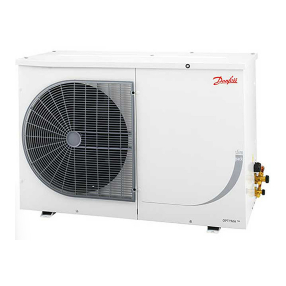
Optyma™ Slimpack
OP-LPHE/MPUE/MPME
MADE IN INDIA
OP-MPUE034MLW04E
A
Code no.:
114X7039
B
C
Application
MBP
D
Refrigerant
(1)
R404A, R507, R22, R448A, R449A
M.W.P. HP
(1) 28 bar
E
LP (1) 7 bar
Voltage
380-400V3N~/50Hz
F
LRA
30,5
MCC
Serial No.
123456CG0514
G
Barcode Serial No:
A: Model
B: Code number
C: Application, Protection
D: Refrigerant
E: Housing Service Pressure
F: Supply voltage, Locked Rotor Ampere,
Maximum Current Consumption
G: Serial Number and bar code
Picture 2
1 – Introduction
These instructions pertain to Optyma
Pack condensing units OP-LPHE/MPUE/MPME
(R22, R404A, R507, R134a, R448A, R449A)) used
for refrigeration systems. They provide necessa-
ry information regarding safety and proper usage
of this product.
The condensing unit includes following:
version W02
• Scroll/reciprocating compressor
• Microchannel heat exchanger
• Dual pressure switches
• Service valves suction/ liquid
• Weather proof housing
• Filter drier
• Receiver with stop valve
• Sight glass
• Solenoid valve
version W04 (without solenoid valve) includes also:
• Phase sequence relay
• Fully pre-wired electrical panel (including main
switch, compressors contactor, overload relay)
• Crankcase heater (OP-LPHE units only)
1 | © Danfoss | DCS (CC)| 2018.07
IP54
(2) R134a
(2) 23 bar
(2) 5 bar
7,5
H
I
J
H: Cable entry ports
I: Suction port
J: Liquid port
K: Microchannel heat exchanger
Mounting bolts
2 – Handling and storage
Slim
• It is recommended not to open the packaging
TM
before the unit is at the final place for installation.
• Handle the unit with care. The packaging al-
lows for the use of a forklift or pallet jack. Use
appropriate and safe lifting equipment.
• Store and transport the unit in an upright position.
• Store the unit between -35°C and 50°C.
• Don't expose the packaging to rain or corrosive
atmosphere.
• After unpacking, check that the unit is com-
plete and undamaged.
3 – Installation precautions
Do not braze as long the condensing unit is
under pressure.
Never place the unit in a flammable atmosphere
Place the unit in such a way that it is not blocking
or hindering walking areas, doors, windows or similar.
• Ensure adequate space around the unit for air
circulation and to open doors. Refer to picture1
for minimal values of distance to walls.
• Avoid installing the unit in locations which are daily
exposed to direct sunshine for longer periods.
• Avoid installing the unit in aggressive and dus-
ty environments.
N
K
Picture 1 : Minimum mounting distances
L
[mm]
250
Installation and servicing of the
condensing
personnel
instructions
engineering practice relating to installation,
commissioning, maintenance and service.
The condensing unit must only be used for
its designed purpose(s) and within its scope of
application.
Under all circumstances, the EN378 (or
other applicable local safety regulation)
requirements must be fulfilled.
The condensing unit is delivered under nitro-
Picture 3
gen gas pressure (1 bar) and hence it cannot
be connected as it is; refer to the «installation»
section for further details.
The condensing unit must be handled with cau-
tion in the vertical position (maximum offset
from the vertical : 15°)
• Ensure a foundation with horizontal surface
(less than 3° slope), strong and stable enough
to carry the entire unit weight and to eliminate
vibrations and interference.
• The unit ambient temperature may not exceed
50°C during off-cycle.
• Ensure that the power supply corresponds to
the unit characteristics (see nameplate).
• When installing units for HFC refrigerants, use
equipment specifically reserved for HFC refri-
gerants which was never used for CFC or HCFC
refrigerants.
• Use clean and dehydrated refrigeration-grade
copper tubes and silver alloy brazing material.
• Use clean and dehydrated system components.
• The suction piping connected to the compres-
sor must be flexible in 3 dimensions to dampen
vibrations. Furthermore piping has to be done
in such a way that oil return for the compres-
sor is ensured and the risk of liquid slug over in
compressor is eliminated.
4 – Installation
• The installation in which the condensing unit is ins-
talled must comply to EEC Pressure directive (PED)
no. 2014/68/EU. The condensing unit itself is not a
L
O
M
M
N
O
[mm]
[mm]
[mm]
650
550
550
units
by
qualified
only.
Follow
these
and
sound
refrigeration
FRCC.PI.022.B0.02
Advertisement

Related Manuals for Danfoss Optyma Slimpack OP-LPHE


Summary of Contents for Danfoss Optyma Slimpack OP-LPHE
- Page 1 • The installation in which the condensing unit is ins- • Avoid installing the unit in aggressive and dus- talled must comply to EEC Pressure directive (PED) ty environments. no. 2014/68/EU. The condensing unit itself is not a FRCC.PI.022.B0.02 1 | © Danfoss | DCS (CC)| 2018.07...
- Page 2 Danfoss recommends that condensing units and tive gloves. cess. oil should be recycled by a suitable company at • Do not overcharge the system. its site. • Never release refrigerant to atmosphere. 2 | © Danfoss | DCS (CC) | 2018.07 FRCC.PI.022.B0.02...
- Page 3 Instructions OP-LPHE048 - 068, OP-MPUE034 - 046 - 057, OP-MPME048 - 060, OP-MPZE060 OP-LPHE067 - 084 - 098, OP-MPUE068 - 080 - 093 - 099 - 108 FRCC.PI.022.B0.02 © Danfoss | DCS (CC) | 2018.07 | 3...
- Page 4 KP 15 060-1154, 060-1220, 060-1261, 060-1263, 060-1 283 LP-man. LP-auto. LP-auto. LP-man. HP-man. HP-man. HP-auto. HP-auto. Convertible reset KP 17B 060-539366, 060-539466 LP-auto. LP-auto. HP-man. HP-auto. 8510198 P03-A © Danfoss Commercial Compressors 03/05 4 | © Danfoss | DCS (CC) | 2018.07 FRCC.PI.022.B0.02...
- Page 5 Fan Speed Controller Compressor Bleeder resistor brown Run capacitor compressor Fan motor Room thermostat grey Start capacitor compressor Start relay Thermostat (crankcase heater) Crankcase heater Compressor contactor Solenoid valve white Fan contactor FRCC.PI.022.B0.02 © Danfoss | DCS (CC) | 2018.07 | 5...
- Page 6 R1, R2 Bleeder resistor brown DUAL Pressure Switch Fuse control circuit Room thermostat grey Start capacitor compressor Compressor Terminals Run capacitor compressor Fan motor Solenoid valve white Crankcase heater Contactor 6 | © Danfoss | DCS (CC) | 2018.07 FRCC.PI.022.B0.02...
- Page 7 Bleeder resistor brown DUAL Pressure Switch Fuse control circuit Room thermostat grey Low pressure switch Compressor Terminals Start capacitor compressor Fan motor Solenoid valve white Run capacitor compressor Contactor Crankcase heater FRCC.PI.022.B0.02 © Danfoss | DCS (CC) | 2018.07 | 7...
- Page 8 Crankcase heater Danfoss can accept no responsibility for possible errors in catalogues, brochures and other printed material. Danfoss reserves the right to alter its products without notice. This also applies to products already on order provided that such alterations can be made without subsequential changes being necessary in specifications already agreed. All trade- marks in this material are property of the respective companies.