Table of Contents
Advertisement
Quick Links
Advertisement
Table of Contents

Related Manuals for ABB ITS2.1


Summary of Contents for ABB ITS2.1
- Page 1 USER MANUAL ITS2.1 Slimline, InlineII and Standalone ITS2...
-
Page 2: Table Of Contents
Technical data ..........................33 Reference to Supplementary documentation ................ 34 XR ITS2.D with ekip display ......................35 13.1 How to plug in the Ekip Display at an XR ITS2.1 unit ..............35 Ekip Display ..........................37 Ekip Display power LED ......................37 14.1 14.2... -
Page 3: Product Overview
ITS2.1 User Manual rev.04/1SEP622750P0001 PRODUCT OVERVIEW Slimline XRG00 Refer the installation instruction for XRG00 ITS2. Slimline XRG1 Refer the installation instruction for XRG1 ITS2. Slimline XRG2 and XRG3 Refer the installation instruction for XRG23 ITS2. -
Page 4: Inline Ii Zhbm00
ITS2.1 User Manual rev.04/1SEP622750P0001 Inline II ZHBM00 Refer the installation instruction for InlineII ZHBM-ITS. Inline II ZHBM123 Refer the installation instruction for InlineII ZHBM-ITS. -
Page 5: Standalone Its
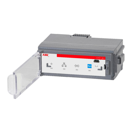
ITS2.1 User Manual rev.04/1SEP622750P0001 Standalone ITS Refer the installation instruction for ITS2.1 Standalone. ITS2.1 Overview TEST/Prg Fuse Blown LED Fuse Blown LED indicates as follows: The TEST/Prg is for use of configuration tool Dark : All fuses are OK Ekip Connect. -
Page 6: Prerequisites
Connect one side of cable B to the programming unit (A) and the other side of cable B to ITS2.1 programing port. Insert the USB (A) to your computers USB port, Ekip T&P unit draws its power from the PC. -
Page 7: The Ekip Connect Software
ITS2.1 User Manual rev.04/1SEP622750P0001 THE EKIP CONNECT SOFTWARE Starting Ekip connect and check for latest update Start Ekip Connect. For a more extensive guide, please refer to Ekip Connect – user manual. Searching for latest version of Ekip Connect and Device Description files are quite easy. However, the... -
Page 8: Basic Parameter Setting
Connect the ITS2.1 via Ekip T&P unit to your computer and start the Ekip Connect software. Click on the ‘SCAN’ button in the T&P section of the ‘CONNECT WITH YOUR DEVICE’ area, the ITS2.1 unit will be detected and then click the ‘Classic view’. - Page 9 ITS2.1 User Manual rev.04/1SEP622750P0001 Slimline XRG Busbar Side Terminal Side Important for XRG 1,2 and 3: The straps on the fuse boards inside the XRG apparatus must be set according to the feeding direction. When changing the power direction, these must be changed...
- Page 10 ITS2.1 User Manual rev.04/1SEP622750P0001 Important for Inline II: The feeding direction can be set by a jumper connector on ITS adapter unit. When changing the power direction, these must be changed accordingly, study chapter 9. 4. Give the ITS unit a unique Modbus slaver address (between 1 – 247).
-
Page 11: Additional Parameter Settings
ITS2.1 User Manual rev.04/1SEP622750P0001 ADDITIONAL PARAMETER SETTINGS The parameter settings below can be set according to special requirements. FUSE BLOWN HANDLING Fuse blown switch open (motor This function is relevant only if the switch is equipped with motor operation. operated device only) If ENABLED the motor will open the switch if one or more fuses are blown. - Page 12 ITS2.1 User Manual rev.04/1SEP622750P0001 ITS STATUS Operating mode If set in REMOTE mode, commands sent on Modbus are accepted. Remote/Local indicate LED in front will be lit. A pushbutton in front of the ITS unit can be used to switch between REMOTE/LOCAL LED mode ALIVE MODE: The power LED in front of the ITS unit is flashing.
-
Page 13: Its Values And Status Information
ITS2.1 User Manual rev.04/1SEP622750P0001 ITS VALUES AND STATUS INFORMATION 5.1 Main page PRODUCT DETAILS CURRENTS Rated current (Ie) 160A, 250A, 400A, 630A, 800A, L1, L2, L3 Measured currents 1000A, 1250A, 1600A, 2000A, 2500A Nominal line voltage Shows configured nominal (Ue) voltage, NOT measured ITS2.1 Serial number... - Page 14 ITS2.1 User Manual rev.04/1SEP622750P0001 SWITCH INFORMATION COMMANDS Switch type Indicates main switch type, Open switch If equipped with motor, Slimline XRG00, Slimline XRG1, switch will open when Slimline XRG2, Slimline XRG3, selected InlineII, OT, OS, Other Close switch If equipped with motor,...
-
Page 15: Alarms
ITS2.1 User Manual rev.04/1SEP622750P0001 Alarms ALARMS Preventive overload Show YES if preventive overload protection occurs protection Fuse blown Show YES if one or more fuses blown Motor operated by Shows YES if the Slimline XRG or OS switch is equipped with motor operation and... -
Page 16: All Measures
ITS2.1 User Manual rev.04/1SEP622750P0001 5.3 All Measures CURRENTS FREQUENCY L1, L2, L3 Actual currents Frequency Actual frequency VOLTAGES V1N, V2N, V3N Actual phase voltages (1) V12, V23, V31 Actual line voltages (1) (1) Accuracy of measured voltages depend on a... - Page 17 ITS2.1 User Manual rev.04/1SEP622750P0001 POWERS ENERGIES P1, P2, P3 Calculated active power (kW) Active energy positive Calculated positive active energy (kWh) Ptot Calculated 3 phase active power Calculated negative active Active energy negative (kW) energy (kWh) Q1, Q2, Q3 Calculated reactive power (kVAR)
-
Page 18: Main Measures
ITS2.1 User Manual rev.04/1SEP622750P0001 5.4 Main Measures STATUS MEASUREMENTS Switch position Indicates switch status is open L1, L2, L3 Actual currents or closed V1N, V2N, V3N Actual phase voltages (1) Fuse blown Indicates that one or more fuses are blown... -
Page 19: Min - Max Measures
ITS2.1 User Manual rev.04/1SEP622750P0001 5.5 Min - max Measures CURRENTS POWERS L1, L2, L3 Actual min - max currents P1, P2, P3 Calculated min – max active power (kW) min - max min - max Calculated min – max 3 phase active... -
Page 20: Modbus Rtu
ITS2.1 User Manual rev.04/1SEP622750P0001 Modbus RTU Modbus RTU communication configuration (Embedded System bus) Slave address Set the address of the connected ITS module, 0~247 selectable, default 247 Baud rate Set the baud rate of the connected ITS module, 9600, 19200 selectable, default 19200... -
Page 21: Modbus Tcp
Ekip com modbus TCP module hardware version Boot version Boot version Mac address It is the address assigned by ABB,it has the following OUI AC:D3:64 Network settings IP address This is the address assigned to the modules at the moment of connection to the network. - Page 22 ITS2.1 User Manual rev.04/1SEP622750P0001 Connections Connected client Ther are three IP Addresses of of the client devices connected to the modules. Static IP Address Force Static IP address Off: Dynamic IP address On: Static IP address Static IP Address Displayed with the static IP Address enabled, it must be selected in order to insert the...
-
Page 23: Multiplug Terminal
ITS2.1 User Manual rev.04/1SEP622750P0001 MULTIPLUG TERMINAL Slimline XRG and Inline II ZHBM ITS multiplug For simplicity of looping several XRG switches together in a multi drop topology, the multiplug terminal is equipped with two rows of terminals. For InlineII ZHBM switches, another multiplug terminal with screw is used and assembled on the ITS adapter. -
Page 24: Standalone Its Module Multiplug
ITS2.1 User Manual rev.04/1SEP622750P0001 Standalone ITS module multiplug For OT&OS and other switches, ITS and adapter module is a standalone product which needs to be connected to switch by external cable. Multiplug to user side Terminal pins definition Terminal Signal... -
Page 25: Modbus Rtu
The parameters presented in the Main Measures menu is available as one contiguous block in the Modbus mapping, making it easy and time saving to read the most common parameters from the ITS2.1 unit. The following parameters can be read:... -
Page 26: Modbus Rtu Cabling
ITS2.1 User Manual rev.04/1SEP622750P0001 7.3 Modbus RTU cabling A shielded twisted pair cable is required for Modbus, we recommend Belden 3105A. Other cables are acceptable if they have equivalent specifications. 7.3.1 Terminating resistors (TR) In order to avoid reflections of the signal, a 120 Ohm terminating resistor must be mounted at both ends of the main cable. -
Page 27: Ekip Com Modbus Tcp Module
Ekip Com Modbus TCP is an accessory module that can function as a communication module integrating the ITS2.1 in an industrial remote supervision and control network. As Communication module, it can be connected to an Ethernet network with the Modbus TCP communication, and allows: ... -
Page 28: Cyber Security
ABB and its affiliates are not liable for damage and/or losses related to such security breaches, unauthorized access, interference, intrusion, leakage and/or theft of data or information. -
Page 29: Power Direction Setting
ITS2.1 User Manual rev.04/1SEP622750P0001 10 POWER DIRECTION SETTING 10.1 Slimline XRG power direction setting Note: Relevant for XRG1,2 and 3 only, XRG00 is made for busbar feed only This is done by placing straps on the Fuse boards located behind the fuses in correct position. - Page 30 ITS2.1 User Manual rev.04/1SEP622750P0001...
-
Page 31: Inlineii Zhbm Power Direction Setting
ITS2.1 User Manual rev.04/1SEP622750P0001 10.2 InlineII ZHBM power direction setting For InlineII ZHBM, the power direction setting is done by connecting a jumper to the outlet on ITS adapter PCBA. When connect to KM6, Busbar Feed is set, when connect to KM5, Terminal Feed is set. -
Page 32: Power Direction For Other Switches
ITS2.1 User Manual rev.04/1SEP622750P0001 10.3 Power direction for other switches The ITS and adapter module is also a standalone product that can be used for OT&OS or other low voltage switchgear. In this application, ITS and adapter module needs to be fixed separately and connected to switch by external cable, refer to the ITS standalone product installation instruction. -
Page 33: Technical Data
ITS2.1 User Manual rev.04/1SEP622750P0001 11 TECHNICAL DATA Technical data for ITS2.1 Input voltage limits Power supply 24 VDC ± 20% Power consumption Functional characteristics Voltage measuring range 10 – 900 VAC Measured current range 0 – 1,3 x In Measuring range temperature 0 –... -
Page 34: Reference To Supplementary Documentation
Inline II ZHBM-ITS Installation instruction 1SEP622739P0001 Follows product ITS2.1 Standalone Module Installation 1SEP622726P0001 Follows product instruction Modbus mapping 1SEB000478 System interface ITS2.1 Technical Application Papers No.9 1SDC007108G0202 Cover ABB SACE’s products, but useful for the ITS2 as well. Bus communication with ABB circuit- breakers... -
Page 35: Xr Its2.D With Ekip Display
ITS2.D with Ekip display is only available for Slimline XRG switch 13.1 How to plug in the Ekip Display at an XR ITS2.1 unit Press in the 3 dedicated areas at the ITS2.1 front panel for fixing the Ekip Display unit. - Page 36 ITS2.1 User Manual rev.04/1SEP622750P0001 2. Plug the Ekip Display into the front of the ITS2.1. (1) Plug first in the guide pin at the left side and then the USB connector ( 2) at the right side 3. Fix the Ekip Display by rotating the closing button to closed position by using a screw driver The ITS2.D can be connected to a laptop for configuration by using the T&P cable unit to the USB connector at...
-
Page 37: Ekip Display
ITS2.1 User Manual rev.04/1SEP622750P0001 14 EKIP DISPLAY 14.1 Ekip Display power LED Power LED (green) will replicate the behaviour of the Power LED on the ITS2 (Power/Alive setting/Wink). 14.2 Ekip Display front overview. Ekip Display LCD view area is divided in 2 separate section: Signalling area and Menu area... -
Page 38: Ekip Display Start Menu
ITS2.1 User Manual rev.04/1SEP622750P0001 14.3 Ekip Display Start Menu Ekip Display Start menu will replace the function of the LED’s placed on the ITS 2.1 front. a ) : 3 status alternatives : Icon Description Communication active on bus and ITS... -
Page 39: Ekip Display Signaling Area
ITS2.1 User Manual rev.04/1SEP622750P0001 14.4 Ekip Display signaling area Signalling area is always present on the Display and it will show the actual status of the ITS device (exception is when Ekip T&P and/or Ekip TT is connected to the display through the lower mini USB connector). -
Page 40: Ekip Display Navigation View (Menu Area)
ITS2.1 User Manual rev.04/1SEP622750P0001 14.5 Ekip Display navigation view (menu area) Enter the Top Level Menu from the Start menu by using the button. Top Level Menu In Table 2 is illustrated the navigation tree of the actual Ekip Display unit. Top Level Menu, Second, Third and Forth Level. - Page 41 ITS2.1 User Manual rev.04/1SEP622750P0001 Table 2: Menu area tree : Top Level Menu Second Level Menu Third Level Menu Energy Power Measure Voltage Current Additional data Open switch FB ( Fuse blown ) Enable / Disable the MOT to disconnect the apparatus when a fuse is blown.
- Page 42 ITS2.1 User Manual rev.04/1SEP622750P0001 Automatic return to Start Menu On : Automatic return to the Start Menu. Off : No automatic return to the Start Menu. Communication Modbus slave address 1-247 Parity Data stop bits. Baud rate. XR size (XR00|XR1|XR2|XR3 ) ...
-
Page 43: Trouble Shooting
ITS2.1 User Manual rev.04/1SEP622750P0001 15 TROUBLE SHOOTING Fault Description Fault Analysis Trouble shooting method Detected current value cannot Switch rated current may not be set Check rated current setting on Ekip connect match to actual current correctly Main page and correct it on ITS2... - Page 44 ITS2.1 User Manual rev.04/1SEP622750P0001 Contact Us ABB Oy P.O. Box 622 FI-65101 Vaasa Finland www.abb.com\fusegear...