Table of Contents
Advertisement
TABLE OF CONTENTS
Introduction .................................................................................................................................................................... 1
Installation ...................................................................................................................................................................... 2
AC Power Hookup .................................................................................................................................................... 2
Audio Connections .................................................................................................................................................... 2
Safety Precautions .................................................................................................................................................... 2
Quick Start Instructions ................................................................................................................................................ 3
Quick Setup .............................................................................................................................................................. 3
With a Mixer .............................................................................................................................................................. 3
Straight into an Amp ................................................................................................................................................. 4
In an Amp's Effects Loop .......................................................................................................................................... 4
Try It Out ................................................................................................................................................................... 5
Selecting Presets ...................................................................................................................................................... 5
DMV-PRO Front Panel Controls and Indicators ..........................................................................................................6
Processors (A) & (B) ................................................................................................................................................. 6
Power ........................................................................................................................................................................ 6
LCD ........................................................................................................................................................................... 6
Edit Button ................................................................................................................................................................ 6
Processor (A) & (B) Encoder / Switch ....................................................................................................................... 7
Routing Button .......................................................................................................................................................... 7
MIDI/Util Button ......................................................................................................................................................... 7
Store Button .............................................................................................................................................................. 7
Bypass Button ........................................................................................................................................................... 7
Preset Encoder / Switch ........................................................................................................................................... 8
Selection Arrow ......................................................................................................................................................... 8
Processor (A) & (B) Meters ....................................................................................................................................... 8
3URJUDPPDEOH 'LJLWDO (IIHFWV 3URFHVVRU
- i -
Advertisement
Table of Contents

Related Manuals for Art DMV Pro


Summary of Contents for Art DMV Pro
-
Page 1: Table Of Contents
In an Amp’s Effects Loop ... 4 Try It Out ... 5 Selecting Presets ... 5 DMV-PRO Front Panel Controls and Indicators ...6 Processors (A) & (B) ... 6 Power ... 6 LCD ... 6 Edit Button ... 6 Processor (A) & (B) Encoder / Switch ... 7 Routing Button ... - Page 2 Routing LEDs ... 8 Unloaded Preset Indicator ... 9 Preset Display ... 9 Special Functions: ... 9 Restoring Presets to Original Factory Settings ... 9 Dry Kill and Global Mix ... 10 Setting Dry Kill and Global Mix ... 11 MIDI Dump ...
- Page 3 Modulated Effects ... 40 Chorus ... 40 Flanger ... 40 Phaser ... 40 Tremolo ... 40 Panner ... 40 Rotary ... 44 MIDI/Util Parameters ... 46 Channel Number / MIDI Dump ... 46 MIDI Map ... 46 Dry Kill / Global Mix ... 47 LCD View Angles / Factory Reset ...47 Reference ...
-
Page 5: Introduction
Thank you for purchasing a DMV-PRO and congratulations! You now own one of the most sophisticated pieces of audio signal-processing technology available. The DMV-PRO uses state-of-the-art DSP techniques combined with A R T’s proprietary Dynamic Engine Allocation (DEA™) software to give you control over a multitude of brand new, stunning effects algorithms—many of which have never been heard before. -
Page 6: Installation
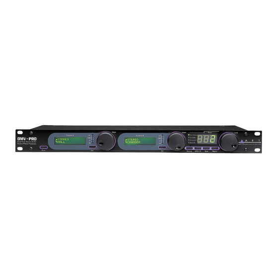
INSTALLATION The DMV-PRO may be used in a variety of setups including with mixer channel inserts, mixers with reverb send and return facilities, and in the effects loop of an instrument or P.A. amplifier. Self-contained in an all-steel, single-height 19” rack-mount enclosure, the DMV-PRO is designed for continuous professional use. Because the unit is compact and lightweight, mounting location is not critical. -
Page 7: Quick Start Instructions
For a mixer with a mono send, use only Input #1. Connect Outputs #1 and #2 to two input channels or the returns on your mixer. The DMV-PRO can be used as two separate, stereo effect-processors. Inputs and Outputs #3 and #4 correspond to the DMV-PRO’s second stereo engine. Again, if your mixer has a mono send, use only Input #3. -
Page 8: Straight Into An Amp
PRO’s Output #2 and the amplifier’s other input. You can also plug a second output from your instrument (or the output from another instrument) into the DMV-PRO’s Input #2. Don’t forget that the DMV-PRO can also be used as two separate, stereo processors, or even as four separate, mono processors. Imagine the Power! IN AN AMP’S EFFECTS LOOP: If you’re patching the DMV-PRO into a guitar (or other instrument) amplifier’s mono effects loop, use one cord... -
Page 9: Try It Out
TRY IT OUT: Turn on your amp or mixer and monitor amplifier. Make sure that your mixer’s or amp’s send level control is turned up and that a signal is being sent to the DMV-PRO. Watch the Meters on the front of the unit. Most of the lights (LEDs) should be on, except for the +6 LED, which should only glow when a really loud, instantaneous signal reaches the unit. -
Page 10: Dmv-Pro Front Panel Controls And Indicators
DMV-PRO FRONT PANEL CONTROLS & INDICATORS PROCESSORS (A) AND (B) The DMV-PRO contains two audio processors, labeled Processor (A) and Processor (B). Each can be operated independently from the other. The controls for each processor operate similarly and are outlined below. -
Page 11: Processor (A) & (B) Encoder / Switch
Encoder’s function between selecting parameters and changing values. For more information on parameters, see page 28. PROCESSORS (A) & (B) ENCODER / SWITCH The first two Encoders are used separately to view and modify their corresponding processor’s parameters and effects. The Encoders can be turned and pressed while editing, and their action is explained in the previous paragraph. -
Page 12: Preset Encoder / Switch
option is available as an effect parameter. See the parameter descriptions on page 28 for more information on bypassing individual effects. PRESET ENCODER / SWITCH currently are viewing, so you will not be hearing the effects or routing that you see on the front panel. To load a preset, press the Preset Encoder. -
Page 13: Unloaded Preset Indicator
UNLOADED PRESET INDICATOR PRESET DISPLAY SPECIAL FUNCTIONS: Restoring Presets to Original Factory Settings The DMV-PRO can overwrite all stored presets with its original factory settings. This process is called a Factory Reset. WARNING: A Factory Reset erases all customized presets. If you have saved some favorite programs, either scroll through their parameters and write them down, or use the MIDI Dump feature to off-load your presets to a MIDI storage device before implementing a factory reset. -
Page 14: Dry Kill And Global Mix
Dry Kill and Global Mix Dry Kill and Global Mix are two related functions that allow you to quickly alter the ratio of wet (processed) and dry (unprocessed) sound coming out of the unit. Normally, the Mix parameter sets this ratio separately for each preset, but by using Dry Kill or Global Mix, you can change these settings for all presets at once. -
Page 15: Setting Dry Kill And Global Mix
Setting Dry Kill and Global Mix: To adjust Dry Kill or Global Mix, press the MIDI/Util button. Turn the Preset Encoder until [ appears on the top line of LCD (A). Turn Encoder (A) to switch the bottom line of LCD (A) between ON and OFF. -
Page 16: Dmv-Pro Rear Panel Controls And Connections
DMV-PRO REAR PANEL CONNECTIONS Despite the DMV-PRO’s sophistication, it’s easy to interface the unit with other equipment. All inputs and outputs are located on the rear panel. Standard ¼” inputs and outputs make patching simple. Note: For best audio quality, always use high-quality cables. The DMV-PRO is designed for line level or instrument operation. -
Page 17: Outputs #1-4
OUTPUTS #1–4 All four Outputs are single-ended (unbalanced) ¼” jacks with low impedance. A preset’s routing determines the use of each Output jack. For example, Cascade and Multi FX Routings do not use Outputs #3 and #4. For more information on the different configurations of the DMV-PRO’s inputs and outputs, see page 26 and the tutorial starting on page 14. -
Page 18: Tutorial
#4 are always controlled by Processor (B). Resource distribution between the inputs and outputs is automatically handled by our proprietary Dynamic Engine Allocation (DEA™) technology. DEA allows for the following creative signal-routing options: Twin Stereo Twin Stereo routing contains two effect-processors with two linked engines each. The result is two true- stereo effects. - Page 19 Cascade Discrete 4 (mono) Multi FX Multi FX routing combines the signal from Inputs #1 and #2 and runs it in series through Engines #1 and #2. The signal is then split and fed to both inputs of linked engines #3 and #4, which are running in true-stereo. The signal from Engine #3 is sent to Output #1 and the signal from Engine #4 is sent to Output #2.
-
Page 20: Tutorial 1: Starting From Scratch And Changing Effects
Processor (B)’s effect since its inputs and outputs correspond to Inputs and Outputs #3 and #4. Mono Routings: Multi FX and Discrete 4 routings have two separate mono effects on one or both of the processors. (See the beginning of this tutorial for more information on routings.) Setting two effects per processor is similar to setting one, like in True Stereo routing. - Page 21 Repeatedly press the Routing button until the Discrete 4 Routing LED is lit. Observe both LCDs. Again, the DMV-PRO has loaded default effects for Discrete 4 routing, but notice that there are now two effects in each LCD. Look at LCD (A). The top line now corresponds to Effect #1 (at Input and Output #1) and the bottom line corresponds to Effect #2 (at Input and Output #2).
-
Page 22: Tutorial 2: Editing Effect Parameters
Follow the instructions: Use the Preset Encoder to select the preset number that you want to overwrite (you don’t have to turn the encoder if you just want to overwrite the current preset). When you are ready, press the Store button to confirm the operation. If you press any button other than Store, or if Store isn’t pressed within 10 seconds, the save command will be aborted. -
Page 23: Tutorial 3: Midi
Repeat this process to switch back and forth between a processor’s effects. Processor (B)’s effects are edited in the same manner. Don’t forget that Processors (A) and (B) are completely independent and can be edited at the same time! -
Page 24: Editing The Global Midi Parameters
this ordering. You could, for example, set a received program change value of 1 to recall DMV-PRO preset #40, a program change value of 2 to recall DMV-PRO preset #5, and a program change value of 3 to also recall DMV-PRO preset #5. Like MIDI Channel, the DMV-PRO’s MIDI Map is set in MIDI/Util Mode and is automatically saved when changed. -
Page 25: An Effect's Midi Parameters
Next, turn Encoder (A) to select an incoming MIDI program change number that you wish to map. This control’s range is from 1 to 128. Turn Encoder (B) to set the corresponding DMV-PRO preset number that will be recalled when the program change number in LCD (A) is received. The range of DMV-PRO preset numbers is from 1 to 100, or OFF to disable a program change number from recalling any DMV-PRO preset. - Page 26 controller’s value linearly corresponds to the key, velocity, or aftertouch value being played. For example, if MIDI CC Number was set to Note On and Mode was set to Continuous, then the controller’s value would equal the key number played. Key, Velocity, or AT Value If Mode is set to Toggle, a second parameter becomes available to set the key, velocity, or aftertouch value that will toggle between the controller values 0 and 127.
-
Page 27: Tutorial 4: Advanced Applications
TUTORIAL 4: ADVANCED APPLICATIONS The Smart Encoder: pressing the Edit and Encoder buttons. Using the encoders this way is called “smart” because parameters can be automatically changed, instead of by having to manually scroll through a series of menus and values. The table below lists all of the Smart Encoder functions and the effect-classes they are available from. -
Page 28: Smart Encoder Programming
Rotary The Rotary Spin High/Low option allows the Encoder to toggle the rotary speed between a high and low spin rate (alternating with each Encoder press). Smart Encoder Programming: Smart Encoder operation is set with an effect’s parameters. To program Processor (A)’s Smart Encoder, first select a preset with a Processor (A) effect and class that uses one of the Smart Encoder functions (see the table above). -
Page 29: Smart Encoder Functions While Editing Reverb, Delay, And Rotary Effects
Smart Encoder Functions while Editing Reverb, Delay, and Rotary Effects: Smart Encoder functions are automatically set up to work while editing reverb, delay, and rotary effects. For Reverb effects, a reverb impulse can be triggered while adjusting any of the reverb’s parameters; this helps you hear the reverb changes as you are making them. -
Page 30: The Dmv-Pro's Adjustable Parameters
Cascade: This routing turns the DMV-PRO into two true-stereo processors. Inputs #1 and #2 feed the first processor (consisting of grouped Engines #1 and #2) and exit at Outputs #1 and #2, and Inputs #3 and #4 feed the second processor (consisting of grouped Engines #3 and #4) and exit at Outputs #3 and #4. - Page 31 Multi FX: Multi FX routing uses the DMV-PRO’s processors to create a three-engine multi-effect chain. Since most engines contain a separate effect, EQ, delay, and dynamics sensing section, the actual multi-effect lengths can be quite long. This routing gives you tons of power to creatively shape your sound.
-
Page 32: Description Of Classes
DESCRIPTION OF CLASSES Each effect has six classes, which are effect variations. The class name generally denotes the application for which the class was optimized. For example, The Vocal class of reverbs is designed to enhance voice-type inputs. Descriptions of all effects and their classes begin on page 31. The following, though, are some class generalizations: Ducking classes use ramped dynamics processing to create smooth “ducking”... - Page 33 Effect Class: Classes are effect variations and are named after the applications they are optimized for. Each effect has six classes and their names, sounds, and adjustable parameters vary based on the effect. (See page 31 for a description of all effects and their classes.) This parameter sets the ratio of unprocessed (dry) sound to processed (wet) sound, with a range from 0% to 100% (0 = all dry, 100 = all wet).
- Page 34 MIDI Parameters Effects can have up to four controller assignments (designated a, b, c, and d) that can modify any of its parameters in real-time. Each of the four assignments has separate settings for the following parameters: CC Channel, MIDI CC Number, Parameter, Value Low Range, and Val. High Range. See the tutorial on page 21 for information on setting the controller assignments.
-
Page 35: Chamber Reverb
The Chamber Reverb simulates a reflective enclosure (perhaps made of wood or concrete) with a sound source at one end and a microphone near the other. By varying the Size parameter from small to large, you can simulate spaces as small as a shower stall and as large as an elevator shaft. This reverb is more reflective and has a more defined echo characteristic than Halls or Rooms. -
Page 36: Reverb Parameters
Instrument The Instrument Reverb is tailored for most solo instruments to maintain their tonal quality. High frequency decays are not limited and low frequencies are controlled to prevent muddiness. An auxiliary gate is available to dynamically process the sound. Concert The Concert Reverb has a neutral high frequency response with a low frequency decay emphasis. - Page 37 (greater than 3 seconds) are usually used for “bigger than life” special effects. Both the Decay and Size parameters should be used together to set the overall impression of the simulated space. Decay Enabled: In the Dynamic Class, this control sets the input level range that switches the Decay amount from the preset value to 0.
- Page 38 Length: Sets the length of the gated reverb, from 50 to 500 milliseconds. Motion: Sets the movement of the reverberation tail. This control is used to help make long decay times sound more natural. When turned on, this control’s range is from 1 to 9 and is normally set at 1, producing a very subtle effect.
-
Page 39: Digital Delay
These algorithms delay a signal in time. The maximum delay length, per channel, is 1.25 seconds. Up to twelve delay taps are available and can be equally and unequally spaced within the span of the delay length. Some delay classes have dynamics sensing, which can use input level to switch the effect in and out or change the Regeneration value. -
Page 40: Delay Parameters
Dynamic The Dynamic Delay uses input level to switch the Regeneration amount between its preset value and 0. DUCKING CLASSIC Delay ±1ms Delay ±1ms Delay ±50ms Delay ±50ms Regeneration Regeneration Number of Taps Number of Taps Shape of Taps Shape of Taps Effect Enabled Attack/Release DELAY PARAMETERS:... - Page 41 starting from the bottom-left speaker. An ‘S’ at the end of the line indicates that both mics pick up sound from both speakers as with normal Stereo miking. An ‘M’ at the end of the line indicates that both mics are acting in Mono and are sonically isolated from the opposite speaker.
-
Page 42: Pitch Transposer
The Pitch Transposer (PT) algorithm can change the base-pitch of a sound. Each PT class contains an auxiliary digital delay that feeds back into the pitch-shift to create falling or rising pitch effects. Some classes also have dynamics sensing, which can use input level to switch the effect in and out or trigger the Whammit! effect (see below). PITCH CLASSES: Micro 2 Voice Micro 2 Voice is the ultimate double tracking algorithm. - Page 43 PITCH PARAMETERS: Buffer Size: This control sets the loop length and splicing characteristics of the PT. Two of the four settings, Smooth- Long and Smooth-Short, are optimized for the smoothest sound, but need a fixed amount of transport delay. The other two settings, Smart-Long and Smart-Short, utilize a looping technique that varies the amount of transport delay based on the Pitch setting.
-
Page 44: Modulated Effects
Chorus, flanger, phaser, tremolo, and panner are modulated effects. They use a Low Frequency Oscillator (LFO) to sweep certain aspects of the effect’s sound. LFO Speed determines the movement (sweep) rate and the LFO Shape determines the sweep pattern. Some of the classes have dynamics sensing, which can use input level to switch the effect in and out or trigger the LFO. -
Page 45: Phaser
Classic, Jazz Chorus, MXR “Grey,” and MXR “Phase 90,” These classes recreate the sound of the “classic” effects. The LFO parameters and sometimes Bandwidth are controlled to produce the characteristic sound and control action. For example, as LFO Speed is increased, Width is automatically adjusted within a musical range. - Page 46 5-Notch Ducking MXR “Phase 90” Delay ±1ms Delay ±1ms Delay ±50ms Delay ±50ms LFO Rate LFO Rate LFO Width LFO Width Regeneration Regeneration LFO Shape LFO Shape LFO Offset LFO Offset Effect Enabled Attack/Release Ducking Classic Delay ± 1ms Delay ± 1ms Delay ±...
- Page 47 Effect Enabled: In Ducking and Gated classes, this control sets the audio input level that controls the gating action of the effect. Signals that fall within its setting (for example, above –10 dB) are heard and ones that are not are muted.
-
Page 48: Rotary
The Rotary effect simulates a 2-way rotating-speaker cabinet with a built in crossover network. Rotating speakers are traditionally used with electric organs, but contemporary uses include with guitars, vocals, drums, and just about any sound that needs some added motion. Since this effect creates a stereo simulation, it is not available with mono effects. - Page 49 Auto Switch Wood Cabinet Spin Up Time Spin Up Time Spin Down Time Spin Down Time Low/High Mix Low/High Mix Speed Adjust Speed Adjust Stereo Spread Rotor Speed Stereo Spread ROTARY PARAMETERS: Dynamic Speed: Dynamic class can automatically switch between low and high rotor speeds, based on input level. The High and Low qualifiers determine the rotor speed when the input level exceeds this control’s setting;...
-
Page 50: Midi/Util Parameters
MIDI/UTIL PARAMETERS The MIDI/Util Parameters affect the whole unit are set in MIDI/Util Mode. To access this mode, press the MIDI/Util button, then turn the Preset Encoder to scroll both LCDs through their separate list of parameters. To change the value of any parameter, turn its corresponding Processor Encoder. -
Page 51: Dry Kill / Global Mix
internally change patches when this happens; it just sets LCD (A)’s program change number to the number that it receives. DRY KILL / GLOBAL MIX Dry Kill Dry Kill is used when running the DMV-PRO with a mixing board in a send/return fashion. (For a complete description, see page 10.) To enable or disable Dry Kill, turn Encoder (A) to switch the bottom line of LCD (A) between ON and OFF. -
Page 52: Reference
REFERENCE: Name TOP 19 Big Stereo Reverb Tight Stereo Reverb Gated Stereo Reverb Sideways Reverb Big Echo Hall Horror Film Nonlinear Delay 1 Rotary Tense Rotary 10 Bass Phaser 11 Phaser 1 12 Phaser 2 13 Water Guitar 14 Flanger 1 15 Flanged Tails 16 Barber Pole Flanger 17 Chorus 1... - Page 53 Chorus 50 Wide Rhode Multi FX 51 MXR "Yellow" Twin Stereo 52 Tri-Chorus Multi FX 53 Direct Strat Multi FX 54 Warm Space Cascade 55 Chorus Spread Discrete 4 56 2X Chorus Cascade 57 Big Chorus + Reverb Cascade 58 Boston (L-R) Chorus Twin Stereo 59 Four Choruses Discrete 4 Flanger...
-
Page 54: Lfo Shapes
LFO SHAPES (two cycles each) EXPONENTIAL The Exponential waveform is not available on Tremolo and Panner effects. SINE TRIANGLE RECTIFIED SINE These graphs are of the available LFO shapes for Chorus, Fanger, Phaser, Tremolo, and Panner effects. The large choice of waveforms will allow you to select the best possible shape for most applications. -
Page 55: Midi Implementation In The Dmv-Pro
INVERTED RECTIFIED SINE SQUARE MIDI IMPLEMENTATION IN THE DMV-PRO Channel Voice Messages The DMV-PRO can respond to Note On, Control Change, Program Change, Channel Pressure, and Pitch Bend messages. In order to respond to these messages, the MIDI Base Channel must be set either to the same channel of the incoming message, or to "ALL.”... - Page 56 Byte Number Value (in hex) (last) The Function ID is one of the following values and is followed by zero or more bytes of data, as implied by the function. Function ID Function Class Unit Handshake Parameter Exchange Unit Status The SysEx message to make the DMV-PRO dump all presets is: F0 1A 0x 21 4B F7 Other MIDI Notes...
-
Page 57: Midi Controllers And Numbers
MIDI CONTROLLERS AND NUMBERS Here’s a list of MIDI Controllers and their numbers, which may help to avoid conflicts if you control the DMV-PRO and other MIDI gear in the same setup. The DMV-PRO displays controller numbers as decimal numbers. The following table lists hexadecimal numbers, their equivalent decimal numbers, and the common uses for these controller numbers in MIDI. -
Page 58: Warranty Information
WARRANTY INFORMATION Limited Warranty Applied Research and Technology, Inc. will provide warranty and Service for this unit in accordance with the following warrants: Applied Research and Technology, Inc. (A R T) warrants to the original purchaser that this product and the components thereof will be free from defects in workmanship and materials for a period of five years from the date of purchase. - Page 59 4) Pack the unit in its original carton or a reasonable substitute. The packing box is not recommended as a shipping carton. Put the packaged unit in another box for shipping. Print the RA number clearly on the outside of the shipping box. Print your return shipping address on the outside of the box. 5) Include with your unit: a return shipping address (we cannot ship to a P.O.
-
Page 60: Dmv-Pro Specifications
DMV-PRO SPECIFICATIONS: A/D converters: D/A converters: Sample Rate: Bandwidth: Dynamic Range: Total Harmonic Distortion: Audio In/Out: Maximum Delay Time: Cascade DSP: Effect Routing Combinations: Effects Algorithms: Twin Stereo, Cascade, Multi FX modes: Discrete 4 mode: MIDI: Other features: Displays: Power requirements: Designed and manufactured in the United States of America. - Page 61 A R T maintains a policy of constant product improvement. A R T reserves the right to make changes in design or make additions to or improvements upon this product without any obligation to install the same on products previously manufactured.