
Related Manuals for Art HQ 15


Summary of Contents for Art HQ 15
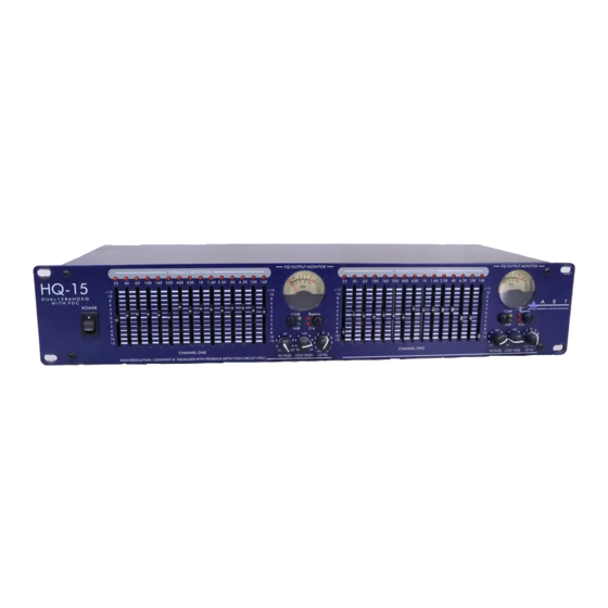
- Page 1 HQ-31 SINGLE CHANNEL 31 BAND 1/3 OCTAVE GRAPHIC EQUALIZER HQ-15 DUAL CHANNEL 15 BAND 2/3 OCTAVE GRAPHIC EQUALIZER USER’S GUIDE...
-
Page 2: General Information
FDC - ART’s FEEDBACK DETECTION CIRCUIT FDC (Feedback Detection Circuitry – designed and developed by ART Engineering) instantly illuminates the corresponding EQ band with the greatest signal. That is, if feedback occurs, FDC identifies the band with the feedback frequency for quick correction. -
Page 3: Installation
INSTALLATION These equalizers are designed for mounting in a standard 19” equipment rack or one of the many rack type portable cases available on the market. The vertical measurements are 3.2 inches. Both models are 8.5 inches in depth. -
Page 4: Signal Levels
Do not connect microphones directly to the equalizer. Microphones require a preamp. CHASSIS GROUNDING The equalizers are equipped with a rear panel Ground lift switch. After setting up your system, if the system exhibits excessive hum or buzzing, the problem may be a ground incompatibility between your equalizer and other equipment in the same system. -
Page 5: Front Panel Controls
to the range selection switch there is a n output level control potentiometer. The level control operates between off and +6dB. Note: If there is too much gain your equalizer has a red LED Clip indicator. The Clip LED illuminates when signals reach 5dB prior to clipping. If this situation occurs and the overload LED flashes occasionally, this is okay, but if the overload LED is steadily on you must readjust the level control. - Page 6 turn on your equalizer BEFORE your power amplifiers are turned on, and always turn off your equalizer AFTER your power amplifiers have been turned off. 2. FILTER LEVEL CONTROLS Each of these sliders controls the output level of each of the 31 (or 15) bandpass filters. A detent at the center position helps center the controls for a flat response.
-
Page 7: Level Control
more natural sound in acoustic situations. 7. LEVEL CONTROL This controls the level of signal coming into the equalizer. Turn this control down if the Clip LED illuminates steadily (meani ng too strong an input signal). Unity gain can be set by turning this knob to the center detent position. - Page 8 10. POWER CORD This cord is used connect the AC power source to your equalizer. CAUTION: Equipment for USA installation includes a captive power cord with a three pin polarized plug. DO NOT REMOVE THE CENTER GROUNDING PIN. 11. FUSE HOLDER This fuse holder contains the AC primary fuse.
- Page 9 FOR BALANCED CONNECTIONS Wire the connector’s as follows: Phone Jack Connection high ring sleeve ground FOR UNBALANCED CONNECTIONS Use 1/4 inch tip-ring-sleeve or mono phone plug connectors or RCA phone jack connectors wired as follows: Phone Jack Connection high ring no connection sleeve ground...
- Page 10 APPLICATIONS Graphic equalizers may be used wherever modification of the frequency contour of a sound system is needed. A graphic equalizer is a solution to any number of sound problems or creative urges. Typical reinforcement application of a two channel equalizer...
-
Page 11: Warranty Information
WARRANTY INFORMATION Limited Warranty Applied Research and Technology will provide warranty and service for this unit in accordance with the following warrants: Applied Research and Technology (A R T) warrants to the original purchaser that this product and the components thereof will be free from defects in workmanship and materials for a period of one year from the date of purchase. - Page 12 SERVICE The following information is provided in the unlikely event that your unit requires service. 1) Be sure that the unit is the cause of the problem. Check to make sure the unit has power supplied, all cables are connected correctly, and the cables themselves are in working condition.
-
Page 13: Specifications
SPECIFICATIONS EQUALIZER Bands Type Accuracy Travel Range INPUTS Type Connectors Impedance Maximum Level OUTPUTS Type Connectors Impedance Maximum Level OVERALL GAIN RANGE RFI filters Passive Bypass Switches Overload LED Threshold High Pass Filter Low Pass Filter Frequency Response THD + Noise IM Distortion (SMPTE) Signal to Noise Ratio Channel Separation... - Page 14 APPLIED RESEARCH & TECHNOLOGY 215 TREMONT STREET ROCHESTER, NEW YORK 14608 USA (716) 436-2720 – Voice (716) 436-3942 – Fax www.artproaudio.com E-mail: cserve@artproaudio.com HQ-15 DUAL CHANNEL 15 BAND 2/3 OCTAVE GRAPHIC EQUALIZER with FDC HQ-31 SINGLE CHANNEL 31 BAND 1/3 OCTAVE GRAPHIC EQUALIZER with FDC HQ15-5004-100...