Siemens SITRANS P Compact Operating Instructions
Pressure transmitter
Hide thumbs
Also See for SITRANS P:
- Operating instructions manual (280 pages) ,
- Brochure & specs (234 pages) ,
- Compact operating instructions (38 pages)
Table of Contents
Advertisement
Quick Links
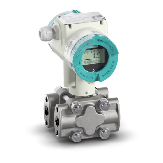
SITRANS P
Pressure transmitter
SITRANS P320/P420
Compact Operating Instructions
7MF03.0 (SITRANS P320 with 4 ... 20 mA/HART)
7MF03.1 (SITRANS P320 with PROFIBUS PA)
7MF04.0 (SITRANS P420 with 4 ... 20 mA/HART)
7MF04.1 (SITRANS P420 with PROFIBUS PA)
01/2021
A5E38874562-AC
Getting started
Introduction
Safety notes
Installing/mounting
Connecting
Commissioning
Service and maintenance
Technical data
Product documentation and
support
Sealing plug / thread
adapter
1
2
3
4
5
6
7
8
A
B
Advertisement
Table of Contents

Related Manuals for Siemens SITRANS P


Summary of Contents for Siemens SITRANS P
- Page 1 Getting started Introduction Safety notes SITRANS P Installing/mounting Pressure transmitter SITRANS P320/P420 Connecting Commissioning Compact Operating Instructions Service and maintenance Technical data Product documentation and support Sealing plug / thread adapter 7MF03.0 (SITRANS P320 with 4 ... 20 mA/HART) 7MF03.1 (SITRANS P320 with PROFIBUS PA) 7MF04.0 (SITRANS P420 with 4 ...
- Page 2 Note the following: WARNING Siemens products may only be used for the applications described in the catalog and in the relevant technical documentation. If products and components from other manufacturers are used, these must be recommended or approved by Siemens. Proper transport, storage, installation, assembly, commissioning, operation and maintenance are required to ensure that the products operate safely and without any problems.
-
Page 3: Table Of Contents
Table of contents Getting started ............................7 Introduction ............................9 Purpose of this documentation .................... 9 Scope of validity of this document..................9 Intended use........................9 Document history ......................10 Product compatibility ......................10 Nameplate layout....................... 11 Checking the consignment....................13 Security information ...................... - Page 4 Table of contents 5.2.2 Connecting the device ....................... 39 5.2.3 Closing the device......................40 Switching on the supply voltage..................41 Commissioning ............................ 43 Basic safety instructions ..................... 43 Commissioning the device ....................44 Application examples ......................45 6.3.1 Gauge pressure, absolute pressure from differential pressure series, and absolute pressure from gauge pressure series...................
- Page 5 Table of contents Technical support....................... 88 Sealing plug / thread adapter ......................89 Intended use of accessory part ................... 89 Safety instructions for accessory part ................. 89 Technical specifications of accessory part ................90 Dimensional drawings for accessory part................91 Index ..............................
- Page 6 Table of contents SITRANS P320/P420 Compact Operating Instructions, 01/2021, A5E38874562-AC...
-
Page 7: Getting Started
Getting started Before you commission the device, observe the following safety notes: • General safety notes (Page 15) • Basic safety notes: Installing/mounting (Page 21) • Basic safety notes: Connecting (Page 35) • Basic safety notes: Commissioning (Page 43) Read the entire device manual to achieve the optimum performance of the device. Procedure 1. - Page 8 Getting started SITRANS P320/P420 Compact Operating Instructions, 01/2021, A5E38874562-AC...
-
Page 9: Introduction
Introduction Purpose of this documentation These instructions are a brief summary of important features, functions and safety information, and contain all information required for safe use of the device. Read the instructions carefully prior to installation and commissioning. In order to use the device correctly, first review its principle of operation. -
Page 10: Document History
Introduction 2.5 Product compatibility With the appropriate configuration and the necessary add-on parts (e.g. limiters and remote seals), you can also use the pressure transmitter for the following measuring tasks: • Level • Volume flow • Mass flow • Volume •... -
Page 11: Nameplate Layout
Introduction 2.6 Nameplate layout Edition Comments Device revision Compatible version of device integration package 09/2018 Manual revised HART 7 SIMATIC PDM V9.0 or higher EDD: 1.00.00 or higher FW: 1.00.08 or higher 06/2018 First edition AMS Device Manager V13 or higher HW: 1.00.00 or higher DTM Pactware V4.1 SP4 or... - Page 12 Introduction 2.6 Nameplate layout Nameplate with approval information The nameplate with approval information is located on the front of the enclosure. Examples Characteristics of the hazardous area Type of protection Group (gas, dust) Maximum surface temperature (temperature class) Device protection level Figure 2-1 Example ATEX Figure 2-2...
-
Page 13: Checking The Consignment
• Do not use damaged or incomplete devices. Security information Siemens provides products and solutions with industrial security functions that support the secure operation of plants, systems, machines, and networks. In order to protect plants, systems, machines and networks against cyber threats, it is necessary to implement –... -
Page 14: Transportation And Storage
The content reflects the technical status at the time of publishing. Siemens reserves the right to make technical changes in the course of further development. -
Page 15: Safety Notes
Safety notes Precondition for use This device left the factory in good working condition. In order to maintain this status and to ensure safe operation of the device, observe these instructions and all the specifications relevant to safety. Observe the information and symbols on the device. Do not remove any information or symbols from the device. -
Page 16: Conformity With European Directives
Safety notes 3.1 Precondition for use 3.1.3 Conformity with European directives The CE mark on the device is a sign of conformity with the following European directives: Electromagnetic compatibility Directive of the European Parliament and of the Council on the harmonization of the laws of the Member States relating to electromagnetic compatibility 2014/30/EU Atmosphère explosible ATEX... -
Page 17: Requirements For Special Applications
Note Operation under special ambient conditions We highly recommend that you contact your Siemens representative or our application department before you operate the device under special ambient conditions as can be encountered in nuclear power plants or when the device is used for research and development purposes. - Page 18 Safety notes 3.3 Use in hazardous areas WARNING Use in hazardous area Risk of explosion. • Only use equipment that is approved for use in the intended hazardous area and labeled accordingly. • Do not use devices that have been operated outside the conditions specified for hazardous areas.
- Page 19 Safety notes 3.3 Use in hazardous areas WARNING Use of the device with intrinsic safety "Ex i" type of protection in a polluted environment. If you open the device on the display side, there is a risk of pollution. The safety of the device for use in hazardous areas is therefore no longer guaranteed.
- Page 20 Safety notes 3.3 Use in hazardous areas SITRANS P320/P420 Compact Operating Instructions, 01/2021, A5E38874562-AC...
-
Page 21: Installing/Mounting
Installing/mounting Basic safety instructions DANGER Pressure applications Danger to personnel, system and environment will result from improper disassembly. • Never attempt to loosen, remove, or disassemble process connection while vessel contents are under pressure. WARNING Wetted parts unsuitable for the process media Risk of injury or damage to device. - Page 22 Installing/mounting 4.1 Basic safety instructions WARNING Incorrect material for the diaphragm in Zone 0 Risk of explosion in the hazardous area. If operated with intrinsically safe supply devices of category "ib" or devices of the flameproof enclosure version "Ex d" and simultaneous use in Zone 0, pressure transmitter explosion protection depends on the tightness of the diaphragm.
- Page 23 • Prevent severe external stresses and loads from acting on the device. Note Material compatibility Siemens can provide you with support concerning selection of sensor components wetted by process media. However, you are responsible for the selection of components. Siemens accepts no liability for faults or failures resulting from incompatible materials.
-
Page 24: Installation Location Requirements
Installing/mounting 4.1 Basic safety instructions 4.1.1 Installation location requirements WARNING Insufficient air supply The device may overheat if there is an insufficient supply of air. • Install the device so that there is sufficient air supply in the room. • Observe the maximum permissible ambient temperature. Refer to the information in the section Technical data (Page 61). -
Page 25: Proper Mounting
Installing/mounting 4.2 Installation (except level) 4.1.2 Proper mounting WARNING Incorrect mounting at Zone 0 Risk of explosion in hazardous areas. • Ensure sufficient tightness at the process connection. • Observe the standard IEC/EN 60079-14. NOTICE Incorrect mounting The device can be damaged, destroyed, or its functionality impaired through improper mounting. - Page 26 Installing/mounting 4.2 Installation (except level) Mounting location Verify that the mounting location meets the following conditions: • Accessible • Close to the measuring point • Vibration-free • Within the permitted ambient temperature values Protect the pressure transmitter from: • Direct heat radiation •...
-
Page 27: Securing The Device With Mounting Bracket
Installing/mounting 4.3 Securing the device with mounting bracket 4. For insulated systems, ensure that you insulate the device as far as possible to the lower edge of the enclosure. In this way, you avoid a defect in the device or the loss of explosion protection for Ex devices. You can find the permissible temperature values in the section Technical data (Page 61). -
Page 28: Installation (Level)
Installing/mounting 4.4 Installation (level) Mount the pressure transmitter as follows: Example 2: Pipe mounting of pressure transmitter (differential pressure series) The mounting bracket for the differential pressure series includes, among other things: • 4 screws • One pipe clamp with nuts •... - Page 29 Installing/mounting 4.4 Installation (level) • Note the effect of the ambient temperature on the measuring accuracy in the section Technical data (Page 61). • For remote seal mounting, observe the notes in the section "Mounting with remote seal" of the operating instructions. Mounting location Verify that the mounting location meets the following conditions: •...
-
Page 30: Mounting On The Container
Installing/mounting 4.4 Installation (level) 4.4.1 Mounting on the container Mounting on open container Formula = ρ · g · h = ρ · g · h Lower filling level Lower range value Upper filling level Upper range value Pressure ρ Density of the measured medium in the container Acceleration due to gravity A line is not required when taking measurements in an open container because the low pressure... - Page 31 Installing/mounting 4.4 Installation (level) Mounting on the closed container (no or little condensate formation) Formula = ρ · g · h = ρ · g · h Lower filling level Lower range value Upper filling level Upper range value Pressure ρ...
- Page 32 Installing/mounting 4.4 Installation (level) Mounting on closed container (heavy condensate formation) Formula = g · (hU · ρ- hV · ρ') = g · (hO · ρ- hV · ρ') Lower filling level Lower range value Upper filling level Upper range value Gland distance ρ...
-
Page 33: Removing
Installing/mounting 4.5 Removing Removing WARNING Incorrect disassembly The following risks may result from incorrect disassembly: - Injury through electric shock - Risk through emerging media when connected to the process - Risk of explosion in hazardous area In order to disassemble correctly, observe the following: •... - Page 34 Installing/mounting 4.5 Removing SITRANS P320/P420 Compact Operating Instructions, 01/2021, A5E38874562-AC...
-
Page 35: Connecting
Connecting Basic safety instructions WARNING Unsuitable cables, cable glands and/or plugs Risk of explosion in hazardous areas. • Use only cable glands/plugs that comply with the requirements for the relevant type of protection. • Tighten the cable glands in accordance with the torques specified in Technical data (Page 61). - Page 36 Connecting 5.1 Basic safety instructions WARNING Lack of equipotential bonding Danger of explosion through compensating currents or ignition currents through lack of equipotential bonding. For devices of intrinsic safety "db", "ec", "tb" or "tc" which are operated in a non-intrinsically safe circuit, observe the following: •...
- Page 37 Connecting 5.1 Basic safety instructions Figure 5-1 Nameplate example: Type 7MF0..0-..-.D..-Z + E20 NOTICE Ambient temperature too high Damage to cable sheath. • At an ambient temperature ≥ 60 °C (140 °F), use heat-resistant cables suitable for an ambient temperature at least 20 °C (36 °F) higher. NOTICE Condensation in the device Damage to device through formation of condensation if the temperature difference between...
-
Page 38: Connecting The Device
Connecting 5.2 Connecting the device Note Improvement of interference immunity • Lay signal cables separate from cables with voltages > 60 V. • Use cables with twisted wires. • Keep device and cables at a distance from strong electromagnetic fields. •... -
Page 39: Connecting The Device
Connecting 5.2 Connecting the device 5.2.2 Connecting the device Procedure ① ⑥ Isolating power supply with integrated load Safety catch ② ⑦ Supply voltage Process connection ③ ⑧ Cable gland Protective conductor connection/ equipotential bonding terminal ④ ⑨ Connecting terminals Ground terminal ⑤... -
Page 40: Closing The Device
Connecting 5.2 Connecting the device ⑦ 1. Connect the device to the system via the existing protective conductor connection observing the torques. – Use a cable with a diameter of 1 … 4 mm ③ 2. Insert the connecting cable through the cable gland ④... -
Page 41: Switching On The Supply Voltage
Connecting 5.3 Switching on the supply voltage Switching on the supply voltage Procedure 1. Connect the device. (Page 39) 2. Switch on the supply voltage. – Product name and firmware version appear briefly on the display. – The measured values are shown on the local display or via remote operation (e.g. SIMATIC PDM). - Page 42 Connecting 5.3 Switching on the supply voltage SITRANS P320/P420 Compact Operating Instructions, 01/2021, A5E38874562-AC...
-
Page 43: Commissioning
Commissioning Basic safety instructions DANGER Toxic gases and liquids Danger of poisoning when venting the device: if toxic process media are measured, toxic gases and liquids can be released. • Before venting ensure that there are no toxic gases or liquids in the device, or take the appropriate safety measures. -
Page 44: Commissioning The Device
Commissioning 6.2 Commissioning the device WARNING Opening device in energized state Risk of explosion in hazardous areas • Only open the device in a de-energized state. • Check prior to commissioning that the cover, cover locks, and cable inlets are assembled in accordance with the directives. -
Page 45: Application Examples
Commissioning 6.3 Application examples Procedure 1. Install the device. Installation (level) (Page 28) Installation (except level) (Page 25) 2. Connect the device. Connecting the device (Page 39) 3. Switch on the supply voltage. Switching on the supply voltage (Page 41) 4. - Page 46 Commissioning 6.3 Application examples Procedure Pressure transmitter above the pressure sam‐ Pressure transmitter below the pressure sam‐ pling point pling point ① ⑥ Pressure transmitter Shut-off valve ② ⑦ Shut-off valve Shut-off valve (optional) ③ ⑧ Shut-off valve to process Condensate vessel (optional) ④...
-
Page 47: Commissioning With Steam Or Liquid
Commissioning 6.3 Application examples 6.3.1.2 Commissioning with steam or liquid Requirement All valves are closed. Procedure ① Pressure transmitter ② Shut-off valve ③ Shut-off valve to process ④ Shut-off valve for test connection or for bleed screw ⑤ Pressure line ⑥... -
Page 48: Differential Pressure And Flow Rate
Commissioning 6.3 Application examples 6.3.2 Differential pressure and flow rate 6.3.2.1 Commissioning in gaseous environments Requirement All shut-off valves are closed. Procedure Pressure transmitter above the differential Pressure transmitter below the differential pressure transducer pressure transducer ① ⑦ Pressure transmitter Blowout valves ②... - Page 49 Commissioning 6.3 Application examples ② 5. Close the stabilizing valve ③ ④ 6. Open the other differential pressure valve ( SITRANS P320/P420 Compact Operating Instructions, 01/2021, A5E38874562-AC...
-
Page 50: Commissioning For Liquids
Commissioning 6.3 Application examples 6.3.2.2 Commissioning for liquids Requirement All valves are closed. DANGER Toxic liquids Danger of poisoning when the device is vented. If toxic process media are measured with this device, toxic liquids can escape when the device is vented. - Page 51 Commissioning 6.3 Application examples Procedure Pressure transmitter below the differential pres‐ Pressure transmitter above the differential pres‐ sure transducer sure transducer ① ⑦ Pressure transmitter Drain valves ② ⑧ Stabilizing valve Gas collector vessels (optional) ③ ④ ⑨ Differential pressure valves Differential pressure transducer ⑤...
-
Page 52: Commissioning With Vapor
Commissioning 6.3 Application examples ④ 9. Partially open the differential pressure valve until liquid escapes without bubbles. 10.Close the differential pressure valve. 11.Close the vent valve (sealing plug with vent valve) on the negative side of the pressure transmitter. ③ 12.Open the differential pressure valve with half a revolution. - Page 53 Commissioning 6.3 Application examples Procedure ① ⑦ Pressure transmitter Drain valves ② ⑧ Stabilizing valve Condensate pots ③ ⑨ Differential pressure valves Differential pressure transducer ④ ⑤ ⑩ Differential pressure lines Insulation ⑥ ⑪ Shut-off valves 3-way valve manifold ⑥ 1.
- Page 54 Commissioning 6.3 Application examples 12.For the lower range value 0 bar, check the zero point (4 mA). ⑤ If the differential pressure lines have equally high condensate columns with the same temperature, the measurement result is error-free. Otherwise, repeat the zero-point adjustment.
-
Page 55: Service And Maintenance
Service and maintenance Basic safety instructions The device is maintenance-free. However, a periodic inspection according to pertinent directives and regulations must be carried out. An inspection can include, for example, check of: • Ambient conditions • Seal integrity of the process connections, cable entries, and cover •... -
Page 56: Cleaning
WARNING Impermissible repair of explosion protected devices Risk of explosion in hazardous areas • Repair must be carried out by Siemens authorized personnel only. CAUTION Hot surfaces Risk of burns during maintenance work on parts having surface temperatures exceeding 70 °C (158 °F). -
Page 57: Defining The Maintenance Interval
Service and maintenance 7.3 Maintenance and repair work 7.3.1 Defining the maintenance interval WARNING No maintenance interval has been defined Device failure, device damage, and risk of injury. • Define a maintenance interval for recurring tests depending on the use of the device and your own experience. -
Page 58: Checking The Seals
Incorrect measured values will be displayed. Changing the seals in a process flange of a differential pressure measuring cell can alter the lower range value. • Changing seals in devices with differential pressure measuring cells may only be carried out by personnel authorized by Siemens. Note Using the wrong seals Using the wrong seals with flush-mounted process connections can cause measuring errors and/ or damage the diaphragm. -
Page 59: Disposal
Service and maintenance 7.5 Disposal See also Decontamination declaration (http://www.siemens.com/sc/declarationofdecontamination) Return document (http://www.siemens.com/processinstrumentation/returngoodsnote) Disposal Devices described in this manual should be recycled. They may not be dis‐ posed of in the municipal waste disposal services according to the Directive 2012/19/EC on waste electronic and electrical equipment (WEEE). - Page 60 Service and maintenance 7.5 Disposal SITRANS P320/P420 Compact Operating Instructions, 01/2021, A5E38874562-AC...
-
Page 61: Technical Data
Technical data Input 8.1.1 Gauge pressure Gauge pressure input Measurand Gauge pressure Measuring span (continuous‐ Measuring span Maximum permissible Maximum test ly adjustable) or measuring operating pressure MAWP (PS) pressure range, max. operating pres‐ 8.3 … 250 mbar 4 bar 6 bar sure (in accordance with 0.83 ... -
Page 62: Gauge Pressure With Front-Flush Diaphragm
Technical data 8.1 Input Gauge pressure measuring limits 30 mbar a/3 kPa a/0.44 psi a • Measuring cell with inert oil 100 mbar a/10 kPa a/1.45 psi a • Measuring cell with FDA-compliant oil Upper measuring limit 100% of max. range (for oxygen measurement: max. 100 bar/10 MPa/1450 psi and 60 °C ambient temperature/medium temperature) Lower range value Between the measuring limits (continuously adjustable) -
Page 63: Gauge Pressure From The Differential Pressure Series
Technical data 8.1 Input Gauge pressure measuring limits with front-flush dia‐ phragm • Measuring cell with FDA-compliant oil 100 mbar a/10 kPa a/1.45 psi a Upper measuring limit 100% of max. range 8.1.3 Gauge pressure from the differential pressure series Gauge pressure input from the differential pressure series Measurand Gauge pressure and differential pressure... -
Page 64: Absolute Pressure From The Gauge Pressure Series
Technical data 8.1 Input Gauge pressure measuring limits from differential pres‐ sure series • Measuring cell with inert oil 30 mbar a/3 kPa a/0.44 psi a 100 mbar a/10 kPa a/1.45 psi a • Measuring cell with FDA-compliant oil Upper measuring limit 100% of max. -
Page 65: Absolute Pressure With Front-Flush Diaphragm
Technical data 8.1 Input Absolute pressure measuring limits from gauge pressure series • Measuring cell with inert oil For process temperature 30 mbar a/3 kPa a/0.44 psi a -20 °C < ϑ ≤ 60 °C (-4 °F < ϑ ≤ +140 °F) For process temperature 60 °C 30 mbar a + 20 mbar a •... -
Page 66: Absolute Pressure From The Differential Pressure Series
Technical data 8.1 Input 8.1.6 Absolute pressure from the differential pressure series Absolute pressure input from the differential pressure series Measurand Absolute pressure Measuring span (continuous‐ Measuring span Maximum permissible Max. permissible ly adjustable) and maximum operating pressure MAWP (PS) test pressure operating pressure (accord‐... -
Page 67: Differential Pressure And Flow
Technical data 8.1 Input 8.1.7 Differential pressure and flow Differential pressure and flow rate input, MAWP 160 bar (2320 psi) Measurand Differential pressure and flow Measuring span (continuous‐ Measuring span Maximum permissible Max. permissible ly adjustable) and maximum operating pressure MAWP (PS) test pressure operating pressure (accord‐... - Page 68 Technical data 8.1 Input For devices with functional safety, the minimum permissible measuring span is limited by the turndown. Therefore, ensure that the configured turndown is no higher than 5:1. Differential pressure and flow rate input, MAWP 420 bar (6092 psi) Measurand Differential pressure and flow Measuring span (continuous‐...
-
Page 69: Level
Technical data 8.1 Input Differential pressure and flow measuring limits Upper measuring 100% of max. range (for oxygen measurement: max. 100 bar/10 MPa/1450 psi and 60 °C ambient tem‐ limit perature/medium temperature) Lower range value Between the measuring limits (continuously adjustable) 8.1.8 Level Level input... -
Page 70: Operating Conditions
Technical data 8.2 Operating conditions Operating conditions Operating conditions for gauge pressure and absolute pressure (from the gauge pressure series) Ambient conditions • Ambient temperature Note: Observe the temperature class in hazardous areas. Enclosure -40 … +100 °C (-40 … +212 °F) Measuring cell with sili‐... - Page 71 Technical data 8.2 Operating conditions Operating conditions for gauge pressure and absolute pressure (from the gauge pressure series) Cell Pressure Temperature range Measuring cell with sili‐ -40 … +100 °C (-40 … +212 °F) cone oil filling Measuring cell with inert oil (gauge pressure) 250 mbar -40 …...
- Page 72 Technical data 8.2 Operating conditions Operating conditions for gauge pressure and absolute pressure with front-flush diaphragm Degree of protection accord‐ Enclosure with appropriate cable IP66/Type 4X ing to IEC/EN 60529/UL50-E gland IP68 (2 hours at 1.5 m) Enclosure with mounted M12 device IP66/Type 4X plug Enclosure with external overvoltage...
- Page 73 Technical data 8.2 Operating conditions Operating conditions for gauge pressure and absolute pressure (from the differential pressure series), differential pressure and flow -50 … +85 °C (-58 … +185 °F) • Storage temperature (with FDA-compliant oil: -20 ... + 85 °C (-4 ...
- Page 74 Technical data 8.2 Operating conditions Operating conditions for level Enclosure -40 … +100 °C (-40 … +212 °F) Measuring cell with sili‐ -40 … +85 °C (-40 … +185 °F) cone oil filling Display -20 … +80 °C (-4 … +185 °F) •...
-
Page 75: Vibration Resistance
Technical data 8.3 Vibration resistance Vibration resistance General operating conditions Gauge pressure series Differential pressure series Aluminum and stainless steel enclo‐ Aluminum and stainless steel enclo‐ sure sure Vibrations (sine) 2 ... 9 Hz at 0.3 mm IEC 60068-2-6 9 ... 200 Hz at 5 m/s² 1 octave/min 5 cycles/axis Continuous shocks (half-sine) -
Page 76: Construction
Technical data 8.4 Construction Operating conditions according to IEC Gauge pressure series Differential pressure series 1)2) 61298-3 (2g normal) Aluminum and stainless steel enclo‐ Aluminum and stainless steel enclo‐ sure sure Vibrations (sine) 10 ... 58 Hz at 0.3 mm IEC 60068-2-6 58 ... - Page 77 Technical data 8.4 Construction Construction for gauge pressure and absolute pressure (from the gauge pressure series) Process connection Stainless steel, material no. 1.4404/316L or Alloy C22, material no. 2.4602 Oval flange Stainless steel, mat. no. 1.4404/316L Seal diaphragm Stainless steel, material no. 1.4404/316L or Alloy C276, material no. 2.4819 •...
- Page 78 Technical data 8.4 Construction Construction for gauge pressure, with flush mounted diaphragm Process connection • Flanges as per EN and ASME • F&B and Pharma flange • BioConnect/BioControl • PMC style Electrical connection Cable inlet using the following screwed joints: •...
- Page 79 Technical data 8.4 Construction Construction for level Weight Approx. 11 … 13 kg (24.2 … 28.7 lb) with aluminum enclosure • In accordance with EN (pressure transmitter with mounting flange, Approx. 13 ... 15 kg (28.7 ... 33 lb) with stainless steel enclosure without tube) •...
-
Page 80: Torques
Technical data 8.5 Torques Construction for level ‑18 NPT female thread and flange connection with mounting thread M10 in ac‐ • Minus side cordance with DIN 19213 (M12 for MAWP 420 bar (6092 psi)) or -20 UNF in ac‐ cordance with EN 61518 Electrical connection Screw terminals Cable inlet using the following screwed joints:... -
Page 81: Display, Keys And Auxiliary Power
Technical data 8.7 Certificates and approvals Display, keys and auxiliary power Display and buttons Keys 4 buttons for operation directly on the device Display • With or without integrated display (optional) • Cover with glass pane (option) Auxiliary power U HART PROFIBUS PA Terminal voltage on pressure transmitter... - Page 82 Technical data 8.7 Certificates and approvals Explosion protection in accordance with HART PROFIBUS PA ATEX Designation II 1/2 G Ex ia/ib IIC T4/T6 Ga/Gb II 1/2G Ex ia IIC T4/T6 Ga/Gb II 2G Ex ib IIC T4/T6 Gb II 2G Ex ib IIC T4/T6 Gb II 3G Ex ic IIC T4/T6 Gc Permissible ambient temper‐...
- Page 83 Technical data 8.7 Certificates and approvals Explosion protection in accordance with HART PROFIBUS PA ATEX Designation II 1D Ex ia IIIC T120 °C Da Permissible ambient temper‐ -40 ... +80 °C (-40 ... +176 °F) -40 … +75 °C (-40 … +167 °F) ature Permissible temperature of -40 …...
- Page 84 Technical data 8.7 Certificates and approvals Explosion protection in accordance with FM (USA) FM19US0155X The permissible operating values can be found in the certificate. Order variants Identification 7MF0..0-..-.B..-Z Class I, Zone 0, AEx ia llC T4/T6 Ga Class I, Zone 1, AEx ib llC T4/T6 Gb lntrinsically Safe (lS) for Class l, DIV 1, Gr.
- Page 85 Technical data 8.7 Certificates and approvals Explosion protection in accordance with FM (USA) Special conditions for use • For type of protection "db": When you use the device as partition wall device in zones that require EPL Ga, isolate the non- intrinsically safe circuit safely from ground, e.g.: through a SELV circuit.
- Page 86 Technical data 8.7 Certificates and approvals SITRANS P320/P420 Compact Operating Instructions, 01/2021, A5E38874562-AC...
-
Page 87: Product Documentation And Support
– "Download as html5, only PC": Open or save the manual in the HTML5 view on your PC You can also find manuals with the Mobile app at Industry Online Support (https:// support.industry.siemens.com/cs/ww/de/sc/2067). Download the app to your mobile device and scan the device QR code. Product documentation by serial number Using the PIA Life Cycle Portal, you can access the serial number-specific product information including technical specifications, spare parts, calibration data, or factory certificates. -
Page 88: Technical Support
Additional information on our technical support can be found at Technical Support (http:// www.siemens.com/automation/csi/service). Service & support on the Internet In addition to our technical support, Siemens offers comprehensive online services at Service & Support (http://www.siemens.com/automation/serviceandsupport). Contact If you have further questions about the device, contact your local Siemens representative at Personal Contact (http://www.automation.siemens.com/partner). -
Page 89: Sealing Plug / Thread Adapter
Sealing plug / thread adapter Intended use of accessory part The sealing plug and the thread adapter (components) can be used for installation in electrical equipment of flameproof" "Ex d" type of protection of groups IIA, IIB, IIC as well as dust protection by enclosure "Ex t"... -
Page 90: Technical Specifications Of Accessory Part
Sealing plug / thread adapter B.3 Technical specifications of accessory part Note Loss of type of protection Changes in the ambient conditions can loosen the component. • As part of the recommended maintenance intervals: Check the compression fitting for tight fit and tighten, if necessary. -
Page 91: Dimensional Drawings For Accessory Part
Sealing plug / thread adapter B.4 Dimensional drawings for accessory part Dimensional drawings for accessory part Sealing plug Ex d, M25 x 1.5, dimensions in mm Sealing plug Ex d, M20 x 1.5, dimensions in mm SITRANS P320/P420 Compact Operating Instructions, 01/2021, A5E38874562-AC... - Page 92 Sealing plug / thread adapter B.4 Dimensional drawings for accessory part ① Sealing ring: Use for dust protection "Ex t" type of protection. Thread adapter Ex d, M25 x 1.5 on M20 x 1.5 and M25 x 1.5 on ½-14 NPT, dimensions in mm Sealing plug Ex d ½...
-
Page 93: Index
Index Ambient temperature, 70, 71, 72, 73 Laws and directives Disassembly, 15 Personel, 15 Layout of nameplate with general information, 11 Blowout valve, 46 Blowout valves, 48 Maintenance, 55 Manuals, 87 Modifications Catalog correct usage, 16 catalog sheets, 87 improper, 16 Certificates, 15, 87 Mounting bracket Cleaning, 56... - Page 94 Index Shut-off valve, 47, 48, 51, 53 Stabilizing valve, 48, 49, 51, 53 Support, 88 Support request, 88 Technical support, 88 partner, 88 personal contact, 88 Test certificates, 15 Threaded adapter Technical specifications, 90 Torque, 90 Torques, 80 Vent valve, 51, 53 Warranty, 14 SITRANS P320/P420 Compact Operating Instructions, 01/2021, A5E38874562-AC...