Task Force Tips Ball Intake Valve Instructions For Installation, Safe Operation And Maintenance
Hide thumbs
Also See for Ball Intake Valve:
Table of Contents
Advertisement
Quick Links
INSTRUCTIONS FOR INSTALLATION, SAFE OPERATION AND MAINTENANCE
WARNING
This instruction manual is intended to familiarize fi refi ghters and maintenance personnel with the operation, servicing and
safety procedures associated with the Ball Intake Valve Series.
This manual should be kept available to all operating and maintenance personnel.
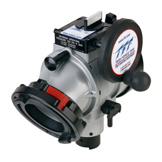
Jumbo Short Ball Intake Valve
AP & AQ Series
Jumbo Short Ball Intake Valve
AP & AQ Series
With Parallel Shaft
OPERATING RANGE:
For Ball Intake Valves
Pressure Max 300 PSI (20 bar)
For Jumbo Ball Intake Valves
Pressure Max 250 PSI (17 bar)
Pressure Min Full Vac.
Hydrostatic Proof Test:
900 PSI (62 bar)
Six seconds from open to close
meets NFPA 1901
slow close requirement.
TASK FORCE TIPS, INC.
MADE IN USA • www.tft.com
©Copyright Task Force Tips, Inc. 2002 - 2011
MANUAL:
Read instruction manual before use. Operation of this device without understanding the manual
and receiving proper training can be dangerous and is a misuse of this equipment. Call 800-348-
2686 with any questions.
Ball Intake Valve
Ball Intake Valve RC
Jumbo Ball Intake Valve
Jumbo Ball Intake Valve RC
Ball Intake Valve
Ball Intake Valve
With Parallel Shaft
Ball Intake Valve RC
3701 Innovation Way, Valparaiso, IN 46383-9327 USA
800-348-2686 • 219- 462-6161 • Fax 219-464-7155
Jumbo Ball Intake Valve
Jumbo Ball Intake Valve
With Parallel Shaft
Jumbo Ball Intake Valve RC
LIA-200 July 30, 2011 Rev13
Advertisement
Table of Contents

Related Manuals for Task Force Tips Ball Intake Valve


Summary of Contents for Task Force Tips Ball Intake Valve
- Page 1 2686 with any questions. This instruction manual is intended to familiarize fi refi ghters and maintenance personnel with the operation, servicing and safety procedures associated with the Ball Intake Valve Series. This manual should be kept available to all operating and maintenance personnel.
-
Page 2: Table Of Contents
4.3 ELECTRICAL INSTALLATION AND WIRING 4.4 ELECTRICAL TESTING 4.5 CHANGING HANDWHEEL TO LEFT SIDE (NON RC MODELS) 4.6 CHANGING HANDWHEEL TO LEFT SIDE (RC MODELS) 4.7 BALL INTAKE VALVE RC MANUAL OVERRIDE 4.8 CHANGING OFFSET OF CRANK HANDLE 4.9 CHANGING COUPLING LOCKOUT 5.0 USE 5.1 INTAKE ELBOW... -
Page 3: Meaning Of Signal Words
NOTICE 2.0 SAFETY Do not use AC current to operate the Ball Intake Valve RC or the Jumbo Ball Intake Valve DANGER RC. The Ball Intake Valve RC and the Jumbo Ball Intake Valve RC are 12 or 24VDC systems ONLY! Using the wrong power source could cause electrocution, resulting in death or serious injury. -
Page 4: General Information
3.0 GENERAL INFORMATION The Ball Intake Valve and the Jumbo Ball Intake Valve are intended for use on the intake manifold of a fi re engine. The valve is kept closed while the water supply from a hydrant or another pumper to the engine is being established. This prevents the pump from sucking air through the intake manifold and losing its prime. -
Page 5: Specifications
The electric motor and other components are ignition sources. The electric BIV should be operated only WARNING in areas where there is adequate ventilation and no hazard of fl ammable vapor buildup. ©Copyright Task Force Tips, Inc. 2002 - 2011 LIA-200 July 30, 2011 Rev13... -
Page 6: Electrical Testing
NOTE: Override knob will only turn in one direction. To ensure proper voltage to the Ball Intake Valve RC, the wiring needs to be checked for proper gauge for the installed length of wire, and for proper termination. Also, ensure that the power source supplying the BIV RC and the grounding are adequate (other electrical loads on a shared circuit with the BIV RC may cause a low-voltage situation). -
Page 7: Changing Handwheel To Left Side (Rc Models)
STEP 2 STEP 1 4.7 BALL INTAKE VALVE RC MANUAL OVERRIDE The Ball Intake Valve RC is motor driven but also has an 11/16” (18mm) Hex override handwheel for operating the valve manually. The override handwheel may also be used in the event of power failure. -
Page 8: Changing Offset Of Crank Handle
Press CLOSE and STOP buttons together and hold for 3 seconds to change to Automatic Mode. Press OPEN and STOP buttons together and hold for 3 seconds to change to manual mode. ©Copyright Task Force Tips, Inc. 2002 - 2011 LIA-200 July 30, 2011 Rev13... -
Page 9: Suction Screen
7.2 RELIEF VALVE FLOW vs. PRESSURE CURVE PRESSURE RELIEF VALVE PERFORMANCE FLOW (LPM) Adjusting Screw 200 PSI SETTING 125 PSI SETTING 50 PSI SETTING Relief Valve Discharge Opening FLOW (GPM) ©Copyright Task Force Tips, Inc. 2002 - 2011 LIA-200 July 30, 2011 Rev13... -
Page 10: Drawings And Parts Lists
8.0 DRAWINGS AND PARTS LISTS Ball Intake Valve - AB & AC Series Optional Parallel Shaft Drive 62 64 62 63 45 46 AC Series RELIEF VALVE PARTS LIST Index Description QTY Part # = Ball Intake Valve 1/2-13 X 1.0 BUTTON HEAD CAP SCREW VT50-13BH1.0... - Page 11 8.0 DRAWINGS AND PARTS LISTS Ball Intake Valve Parts List - AB & AC Series Index Description QTY Part # Index Description QTY Part # BIV BODY - POWDER COAT A1015 A4115 COUPLING HEAD STORZ 5" X 5.25PSF O-RING-236 3-1/4 ID 1/8 C/S VO-236 INSERT RING STORZ 5”...
- Page 12 8.0 DRAWINGS AND PARTS LISTS Jumbo Ball Intake Valve - AX & AZ Series Optional Parallel Shaft Drive X631 Blank Cap AZ Series AX Series ©Copyright Task Force Tips, Inc. 2002 - 2011 LIA-200 July 30, 2011 Rev13...
- Page 13 8.0 DRAWINGS AND PARTS LISTS Jumbo Ball Intake Valve Parts List - AX & AZ Series INDEX DESCRIPTION QTY PART # INDEX DESCRIPTION QTY PART # 6" BALL INTAKE BODY A1086 DETENT PIN A1560 HALF BALL STAINLESS STEEL 8" DIA...
- Page 14 8.0 DRAWINGS AND PARTS LISTS Jumbo Ball Intake Valve - AP & AQ Series Optional Parallel Shaft Drive AQ Series ©Copyright Task Force Tips, Inc. 2002 - 2011 LIA-200 July 30, 2011 Rev13...
- Page 15 8.0 DRAWINGS AND PARTS LISTS Jumbo Ball Intake Valve Parts List - AP & AQ Series Index Description Qty Part # STORZ W/LOCK 4" COUPLING SUBASSEMBLY A4124 6" BALL INTAKE BODY A1086 STORZ W/LOCK 5" COUPLING SUBASSEMBLY A4125 HALF BALL STAINLESS STEEL 8" DIA A1088S STORZ W/LOCK 6"...
- Page 16 1/4-20 X ½ BUTTON HEAD CAP SCREW VT25-20BH500 MOTOR ENCLOSURE TUBE Y4641 CIRCUIT BOARD STANDOFF Y5538 VALVE MOTOR BOARD A5825 MOTOR ENCLOSURE CAP Y4642 SMALLEY RING V4295 ©Copyright Task Force Tips, Inc. 2002 - 2011 LIA-200 July 30, 2011 Rev13...
- Page 17 GEAR BUSHING A1548 O-RING-214 VO-214 DOUBLE GEAR A1554 1/4-20 X 3/4 SOCKET HEAD SCREW VT25-20SH750 BUSHING A1549 3/8-16 X 1 1/2 SOCKET HEAD SCREW VT37-16SH1.7 INNER TRUNNION A1553 ©Copyright Task Force Tips, Inc. 2002 - 2011 LIA-200 July 30, 2011 Rev13...
-
Page 18: Trouble Shooting
(1998 edition), if dissimilar metals are left coupled together an anti-corrosive lubricant should be applied to the threads. Also the coupling should be disconnected and inspected at least quarterly. Any alterations to the Ball Intake Valve and its markings could diminish safety and constitutes CAUTION a misuse of this product. -
Page 19: Templates
INSTALLER CAN USE FLAT OR #4 SCREWS TO STOP ROTATION 0.964" (24.5mm) 1/8" (3mm) DIA SQUARE (4) PLACES Ø1.00" (25mm) 0.919" (23mm) OPTIONAL FLAT HOLE LOCATIONS FOR QUICK CONNECT PLUG TEMPLATE 4.2B ©Copyright Task Force Tips, Inc. 2002 - 2011 LIA-200 July 30, 2011 Rev13... -
Page 20: Warranty
Task Force Tips, Inc., 3701 Industrial Way, Valparaiso, Indiana 46383-9327 USA (“TFT”) warrants to the original purchaser of its Ball Intake Valve and Ball Intake Valve RC (“equipment”), and to anyone to whom it is transferred, that the equipment shall be free from defects in material and workmanship during the fi...