Task Force Tips Ball Intake Valve Instructions For Safe Operation And Maintenance
Hide thumbs
Also See for Ball Intake Valve:
Table of Contents
Advertisement
Quick Links
INSTRUCTIONS FOR SAFE OPERATION AND MAINTENANCE
WARNING
This instruction manual is intended to familiarize firefighters and maintenance personnel with the operation,
servicing and safety procedures associated with the Ball Intake Valve, Ball Intake Valve RC, Jumbo Ball Intake
Valve and/or Jumbo Ball Intake Valve RC.
This manual should be kept available to all operating and maintenance personnel.
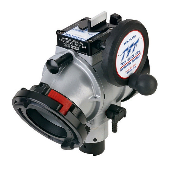
Ball Intake Valve
Jumbo Ball Intake Valve
TASK FORCE TIPS, Inc.
MADE IN USA •www.tft.com
©Copyright Task Force Tips, Inc. 2002-2006
MANUAL:
Read instruction manual before use. Operation of this device without understanding the
manual and receiving proper training is a misuse of this equipment. A person who has
not read and understood all operating and safety instructions is not qualified to operate
the Ball Intake Valve, Ball Intake Valve RC, Jumbo Ball Intake Valve and/or Jumbo Ball
Intake Valve RC.
OPERATING RANGE:
Pressure Max 250 PSI
Pressure Min Full Vac.
Hydrostatic
Proof Test:
Six seconds from
open to close
meets NFPA 1901
slow close requirement.
Ball Intake Valve
Ball Intake Valve RC
Jumbo Ball Intake Valve
Jumbo Ball Intake Valve RC
900 PSI
2800 E. Evans Ave, Valparaiso, IN 46383-6940 USA
800-348-2686 • 219-462-6161 • Fax 219-464-7155
Ball Intake Valve RC
Jumbo Ball Intake Valve RC
LIA-200 October 19, 2006 Rev 09
Advertisement
Table of Contents

Related Manuals for Task Force Tips Ball Intake Valve


Summary of Contents for Task Force Tips Ball Intake Valve
- Page 1 Intake Valve RC. This instruction manual is intended to familiarize firefighters and maintenance personnel with the operation, servicing and safety procedures associated with the Ball Intake Valve, Ball Intake Valve RC, Jumbo Ball Intake Valve and/or Jumbo Ball Intake Valve RC.
-
Page 2: Table Of Contents
2.0 SAFETY Do not use AC current to operate the Ball Intake Valve RC or the Jumbo Ball Intake Valve RC. The DANGER Ball Intake Valve RC and the Jumbo Ball Intake Valve RC are 12 or 24VDC systems ONLY! Using the wrong power source could cause electrocution, resulting in death or serious injury. -
Page 3: General Information
3.0 GENERAL INFORMATION The Ball Intake Valve and the Jumbo Ball Intake Valve are intended for use on the intake manifold of a fire engine. An electric remote controlled (RC) model allows the valve to be operated from a remote location. The valve is kept closed while the water supply from a hydrant or another pumper to the engine is being established. -
Page 4: Specifications
If knob cannot be turned and motor continues to operate, then the voltage supply or wiring is not adequate. Check connections and voltage connection point, rewire if necessary. NOTE: Override knob will only turn in one direction. ©Copyright Task Force Tips, Inc. 2002-2006... -
Page 5: Changing Handwheel To Left Side Rc
NOTE: Remove set screw that is in hole for the button head screw and reinstall the set screw on the other side. The set screw plugs the hole to keep dirt from entering the gearbox. STEP 4 STEP 3 STEP 2 STEP 5 STEP 1 ©Copyright Task Force Tips, Inc. 2002-2006... -
Page 6: Use
4.5 BALL INTAKE VALVE RC MANUAL OVERRIDE 11/16” (18mm) Hex The Ball Intake Valve RC is motor driven but also has an override handwheel for operating the valve manually. The override handwheel may also be used in the event of power failure. If... -
Page 7: Air Vent And Water Drain
Do not cap or plug discharge opening. 7.2 RELIEF VALVE FLOW vs. PRESSURE CURVE PRESSURE RELIEF VALVE PERFORMANCE Adjusting 700 FLOW (LPM) Screw 200 PSI SETTING 125 PSI SETTING Relief Valve Discharge Opening 50 PSI SETTING 200 FLOW (GPM) ©Copyright Task Force Tips, Inc. 2002-2006... -
Page 8: Drawings And Parts Lists
8.0 DRAWINGS AND PARTS LISTS Exploded View of Ball Intake Valve 62 64 62 63 45 46 AC Series AB Series ©Copyright Task Force Tips, Inc. 2002-2006... - Page 9 8.0 DRAWINGS AND PARTS LISTS Ball Intake Valve Parts List Index Description Part # BGIV BODY - POWDER COAT A1015 O-RING-236 3-1/4 ID 1/8 C/S VO-236 BACK RING STAINLESS STEEL A1201S VALVE SEAT A1520 PLASTIC STRIP 7.00" A1290 SEAL RETAINER A1521S COUPLING 5.0"NHF X PSF7.0-NFS...
- Page 10 A1160 O-RING-231 2-5/8 ID 1/8 C/S VO-231 QUAD RING 422 1.5 ID X 1/8 C/S VOQ-4222 SPRING SEAT A1166 RELIEF SPRING A1170 SMALLEY RING V4210 ADJUSTING SCREW A1167 SPRING HOUSING A1164 COVER PLATE/CAP X631 ©Copyright Task Force Tips, Inc. 2002-2006...
- Page 11 8.0 DRAWINGS AND PARTS LISTS Exploded View of Motor Assembly for Ball Intake Valve RC and Jumbo Ball Intake Valve RC INDEX DESCRIPTION PART # 1/4-28 X 5/8 SOCKET HEAD CAP SCREW VT25-28SH625 REDUCER COVER A1097 BUSHING NYLON X252 38LINK ROLLER CHAIN...
- Page 12 8.0 DRAWINGS AND PARTS LISTS Exploded View of Jumbo Ball Intake Valve ©Copyright Task Force Tips, Inc. 2002-2006...
- Page 13 8.0 DRAWINGS AND PARTS LISTS Jumbo Ball Intake Valve Parts List ©Copyright Task Force Tips, Inc. 2002-2006...
-
Page 14: Trouble Shooting
NFPA 1962 (1998 edition), if dissimilar metals are left coupled together an anti-corrosive lubricant should be applied to the threads. Also the coupling should be disconnected and inspected at least quarterly. Any alterations to the Ball Intake Valve and its markings could diminish safety and CAUTION constitutes a misuse of this product. -
Page 15: Templates
TEMPLATE 4.2A INSTALLER CAN USE FLAT OR #4 SCREWS TO STOP ROTATION 0.964" (24.5mm) 1/8" (3mm) DIA SQUARE (4) PLACES Ø1.00" (25mm) 0.919" (23mm) OPTIONAL FLAT CUT OUT FOR QUICK CONNECT PLUG TEMPLATE 4.2B ©Copyright Task Force Tips, Inc. 2002-2006... -
Page 16: Warranty
Task Force Tips, Inc., 2800 East Evans Avenue, Valparaiso, Indiana 46383 ("TFT") warrants to the original purchaser of its Ball Intake Valve, Ball Intake Valve RC, Jumbo Ball Intake Valve, Jumbo Ball Intake Valve RC ("equipment"), and to anyone to whom it is transferred, that the equipment shall be free from defects in material and workmanship during the five (5) year period from the date of purchase.